Altair Multi Body Solutions 2021 Release Notes
Highlights
- MotionView Python API
- MotionSolve-EDEM co-simulation - Flex body interaction
- Track builder
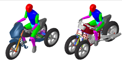
- New Leaning Three-Wheel Example Models
- New 1D Anti-Lock Braking and Electric Powertrain Models
- Full-Vehicle Event Updates
- DELFT-TYRE (MF-Tyre/MF-SWIFT) Version update
- Other enhancements
- Resolved Issues
MotionView Python API
MotionView now has a Python interface for creating a model. Using the API, MotionView models can be created, queried, and modified through Python. This functionality opens avenues for modeling and customization, leveraging the power and flexibility of the Python language.
The API documentation for each entity with examples is available in theMotionView Python Reference Guide.
MotionView-EDEM Cosimulation Updates

Figure 1.
New to this cosimulation is the capability for component model synthesis (CMS) based flexible bodies to interact with DEM particles. CMS flexible bodies can represent body deformation in the linear range. Reaction forces due to contact between DEM particles and the flexible body are simulated that lead to strain and stresses within the flexible body. Absolute nodal coordinate formulation (ANCF) based non-linear finite elements (NLFEs) are not supported to interact with DEM particles at this point. This feature will be part of a future release.
In MotionView, it is possible to transfer a flexible body to EDEM as well as add it to the EDEM system for interaction.
MotionView now uses obj files in the background to transfer geometry to EDEM. This change significantly speeds up the transfer process. In addition, there is a new option in the EDEM system panel to pick either a Body or a Graphic. Due to this enhancement, all graphics belonging to a body can be selected at once. For more details, please refer to the Bulk Material Interaction topic.
In the previous version, MotionSolve required to have additional EDEM installation on the same machine where MotionSolve is installed. From this release, the required binaries have been packaged into MotionSolve such that an EDEM installation on the same machine alongside MotionSolve is not required anymore for cross-platform/multi-machine co-simulation.
Track Builder
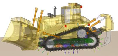
MotionView/MotionSolve includes a new continuous track plug-in for tracked vehicles, such as bulldozers, excavators, robots, snowmobiles, and military vehicles. The track plug-in automatically assembles a continuous band of treads or track plates driven and suspended by two or more wheels, that can interact with soft-soil surface.
This utility assists in building the track linkage along with other components in the track system such as sprockets, rollers and idlers. The tool is available under the Model menu.
MotionSolve entails all necessary elements, such as the soft-soil model and the interaction with the track links, to simulate a tracked vehicle. The track builder can be accessed from MotionView through the Model menu.
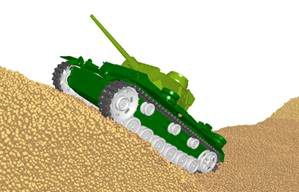
Figure 2. Tracked vehicle driving on soft soil

Figure 3. Tracked vehicle driving on particles in EDEM
New Leaning Three-Wheel Example Models

- Known Issues
- The model graphics are not release intent and will be updated before release.
New 1D Anti-Lock Braking and Electrict Powertrain Models
- Anti-Lock Braking
-
Anti-lock braking systems sense impending wheel lock-up under braking and modulate hydraulic brake pressure to individual brake calipers to prevent wheel lock. The 1D Anti-Lock Brake system takes wheel speeds, vehicle longitudinal acceleration, and front and rear master cylinder hydraulic pressures as feedback from the vehicle model and outputs hydraulic pressures for the brake calipers. The Anti-Lock Brake system consists of a control block and hydraulic block. The control block employs the wheel speeds and the vehicle longitudinal acceleration to estimate the tire longitudinal slips and the modulates the hydraulic control valves to reduce hydraulic pressures to specific wheels as need to limit slip.
- Electric Powertrain
-
The Two-Wheeler and Car/Light Truck libraries now include electric powertrain systems for Battery Electric Vehicles (BEVs). The electric powertrain system maps throttle and brake inputs from the driver to demanded torque (either for traction or regeneration). The demanded torque and the motor shaft rotational speed are input to the 1D motor, inverter, and battery models encapsulated within an FMU. Output from the FMU is the actual torque produced or absorbed by the motor which may differ from the demanded torque due to current or power limits. The actual torque is applied to the driveline to accelerate or decelerate the vehicle.
The MDL system wrapping the FMU 1D motor, inverter, and battery models includes the motor’s stationary and rotating mass and inertia, and also the battery mass and inertia which is a significant portion BEVs total mass and inertia. Finally, the electric motors’ torque-speed characteristic is read from an external file for use in Altair Driver’s feedforward speed and acceleration control.
Full-Vehicle Event Updates
- Road Selection
- All event editors now contain a Road Parameters section with an option
menu for selecting the road. You can choose to run the event on a flat
road, run the event on a road file you select in the event editor, or
run the event on the road files specified from the AutoTires.

Figure 5. - Road Graphics
- In addition, when you select to run on a flat road the event editor
offers you the option to create road and path graphics. A road settings
dialog give you control over the size and colors of the graphics.

Figure 6. Single Lane Change Event with Road and Path Graphics - Driver PID Gains
- All event editors now offer the ability to set Driver gains. The gains available depend on the vehicle type. For leaning vehicles (for example, motorcycles and scooters) you can set the lean angle and lateral path PID gains. For all vehicles you add and set the gains for a longitudinal PID controller to improve speed and acceleration control.
MDL Library Enhancements
- Two-Wheeler Library
-
- A classic telescopic front fork system sized for scooters is a new option available in the two-wheeler assembly wizard.
- The stiffness and damping values in scooter front and rear suspensions systems are updated provide more realistic ride-frequencies and eliminate overdamping.
- Truck Library
- The Truck Library adds an option for Electric Power Assisted System (EPAS) to the pitman arm steering system. The assist torque acts on the input shaft to the steering gear in parallel to the torque that comes from the driver.
DELFT-TYRE (MF-Tyre/MF-SWIFT) Version-up to 2020.1.1
DELFT-TYRE from Siemens distributed with Altair HyperWorks is updated to Simcenter Tire version 2020.1.1 from version 6.2.2. Simcenter Tire is Siemen’s rebranding of TASS/TNO’s DELFT-TYRE. DELFT-TYRE version 2020.1.1 is thread-safe and available for real-time operating systems, MotionSolve models employing DELFT-TYRE version 2020.1.1 typically run faster than those employing DELFT-TYRE 6.2.2 while producing the similar results. Most users of DELFT-TYRE with MotionSolve should only notice faster execution. However, there are some differences that long time users of DELFT-TYRE need to be aware of: these are described the “Differences” section below.
- Differences
- DELFT-TYRE Version 2020.1.1 shows the following differences with respect
to MF-Tyre/MF-Swift 6.2.
- Un-Supported Fit Types
- DELFT_TYRE 2020.1.1 drops support for the following versions
of the Magic Formula equations (fit types):
FITTYP = 21 MF-Tyre 5.2 Magic Formula equations FITTYP = 50 MF-Tyre 6.0 Magic Formula equations Further, the tire property parser is stricter than in previous versions of DELFT-TYRE, so it is typically not possible to change the FITTYP in a file from an old version to a new version. If you have tire property files using these un-supported fit types, please consider using the newer example tire property files from the HyperWorks installation (see ..Altair\2021.0\hwdesktop\hw\mdl\autoentities\properties\Tires\MF_SWIFT), or contact Siemens to have your older tire property files refitted.
- Property File Header Block
- DELFT-TYRE 2020.1.1 requires using the block name [MDI_HEADER] as the first block in the tire property file. Some example tire property files in older versions of HyperWorks use [ALTAIR_HEADER] as the first block and DELFT-TYRE 2020.1.1 reports an error reading these files. Replacing ‘ALTAIR_HEADER’ with ‘MDI_HEADER’ corrects the error.
- Property File Units
- Only SI units are allowed as input in the tire property file. Automatic conversion of non-SI units to SI units is not supported.
- 2D Enveloping Contact
- The 2D enveloping contact method is deprecated (USEMOD = 4xx).
- Motorcycle Contact Mode
- In DELFT-TYRE 2020.1.1 the values of the parameters MC_CONTOUR_A and MC_CONTOUR_B determine if a tire is a motorcycle tire and enable motorcycle behavior. The motorcycle contact mode is deprecated (USEMOD = 2xx) and it is no longer possible to treat car tires as motorcycle tires or vice versa.
- TNO Roads
- DELFT_TYRE 2020.1.1 drops support of 2D ’TNO Roads’ in rdf format (for example PlankRoad, PolylineRoad, and SineRoad) and USEMOD = 3xx for employing a tire’s distance travelled as an ordinate for 2D roads. Where possible 2D ‘TNO Roads’ are replaced by Altair’s 2D roads.
- Known Issues
- Setting the road friction multiplier MU in TNO flat road has no effect in DELFT-TYRE version 2020.1.1. DELFT-TYRE version assumes MU = 1.0 ignoring user input.
CDTire Version Up to v4.2.10
With HyperWorks 2021 CDTire is updated from version 4.2.2 to 4.2.10. See the CDTire documentation for additional information.
CDTire for MotionSolve Now Employs Altair Licensing
With the HyperWorks 2021 release, CDTire now uses Altair Licensing. If you previously purchased CDTire for MotionSolve or CDTire for MotionSolve with resizing and your maintenance is paid, your HyperWorks 2021 license will enable use of CDTire with MotionSolve. Going forward this means you no longer need to run the CDTire license server and install a separate CDTire license. Note there is no unit draw for CDTire. If you purchased CDTire for MotionSolve, and you Altair License does not enable usage of CDTire, please contact your Altair Account Representative.
Other Enhancements
- Geometry Import
- Import geometry process has been simplified. The geometry is imported directly into MotionView without the need for additional inputs. Material assignment can be made through right click context in the graphics area upon selection of graphics.
- Hiding Implicit Graphics in Systems
- An attribute draw_graphic is available at the system entity level to show/hide the implicit graphics of entities within the system. Usage: *Set(sys.draw_graphic, false), where sys is the variable name of the system. If set to false, all implicit graphics within the system including child systems are hidden.
- Missing Graphic Files
- File Graphics with missing reference file when not used in contacts will not prevent export of the solver deck. A warning is now issued instead of an error.
- User Defined Solver String
- User defined solver string is now supported in MotionView.
- Updates to Multi-Disciplinary Tools
-
- The old "points2mesh" macro is replaced by NEW "points2nodes" and "points2fpoints" macros
- Replacement of old "roller2Dcam_*" systems by NEW "roller2cam" macro
- New Seal feature
- Updates to geometry features in HyperMesh
- simplification of "apply2displayed" and "apply2marked" macros management
- improved "line2motion" macro management in "apply2marked" mode
- FMU Updates
- FMU panel and the Edit dialogs have been updated. Reload FMU is now
available in the FMU entity panel. A Reset to defaults button is
available to reset the inputs and parameters individually.
The MDL statements for FMU have been revamped. Input and Parameter array arguments have been removed from *FMU while new data statements *SetFMUInputs and *SetFMUParameters are provided. MotionView maintains backward compatibility. Support for older usage of statements is continued. MotionView automatically saves with the newer syntax and statements.
- Virtualization of Joints
In Multibody Dynamics, a regular, or ideal joint can be defined as a set of algebraic constraint equations that are incorporated into the overall equations of motion. Virtualization of most regular joints is now supported where the algebraic constraints are converted into a “soft”-coupling between constrained bodies. This is an experimental feature. From a user’s perspective, a regular and a virtual joint provide the same kinematics and dynamics, with the exceptions that a virtual joint does not introduce constraint redundancy. Furthermore, virtual joints work with joint friction just as regular joints, which makes them a good replacement for bushings, where friction has to be modeled.
Use the environment variable HW_MV_EXPERIMENTAL=VIRTUAL_CONSTRAINTS to enable the use of Virtual option for the joint/motion in the MotionView panel.- Support OML Based User Subroutines
-
Since release 2020.1, MotionSolve supports subroutines that are scripted in the OpenMatrix Language (OML) using an embedded OML interpreter. The basic OML interpreter supports the basic OML syntax, but does not include/support any of the additional toolboxes and libraries.
With this release, MotionSolve connects with the installation of Altair Compose to interpret OML-based subroutines. This provides users with access to hundreds of powerful math operations and built-in function that are entailed in Altair Compose, ranging from linear algebra, statistics, differential equations, signal processing, control systems, polynomial fitting, to optimization.
If no Compose installation exist, then MotionSolve falls back to its original embedded OML interpreter. OML-based subroutines are supported on Windows only. A Linux support for OML subroutines will be provided in future releases.
Due to the similarity of the OML and MATLAB scripting language, the embedded OML interpreted can be used to interpret MATLAB scripts as well, as long as the scripts do not reference any additional toolboxes and libraries. In this case, MotionSolve looks for a MathWorks’s MATLAB installation to interpret *.m files first, but if the respective interpreter is not installed, MotionSolve uses its own basic OML interpreter to run *.m scripts instead.
- Proximity Sensor
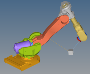
- A proximity sensor monitors the minimum separation between two bodies.
The sensor tracks the state of interference of the two bodies, the
minimum distance between them, and the coordinates of a pair of closest
points. For this release, the computationally performance of this sensor
has been improved. Furthermore, the refinement level for the graphics
has been dropped from the input. Previously, only point to point
distances have been calculated for meshed geometries. The new version
also calculates minimal distance between triangles/lines/point
combinations and thus a refinement is not needed anymore. Also, the
sensor tries to use an analytical approach for primitive geometries
where applicable.

Figure 7. Measuring continuously the proximity of a robot arm to a box that needs to be picked up - Python File Input MotionSolve Plant in Activate
- A MotionSolve plant in Altair Activate can now accept a MotionSolve
python file as an input file. This python file defines the model and
command statements using the python based MSolve-API. The mdl and xml
files remain as valid input files too.
Since the motion engine in Altair InspireMotion is driven by MotionSolve, models can now be exported from InspireMotion as a python files and imported into Activate as a MotionSolve plant to run co-simulations. Plant inputs and outputs of certain Inspire components, such as a motor, are then available within Activate to be connected to other Activate components, for example a controller.
- MotionSolve and OptiStruct Co-simulation - General
-
MotionSolve can interface with Altair OptiStruct. Flexible bodies that undergo plastic deformation or contact with other flexible bodies in OptiStruct can be defined. These bodies can be connected with larger mechanical systems in MotionSolve via interface nodes (spherical joints). In this release, a new stabilization algorithm has been introduced at the interface nodes between MotionSolve and OptiStruct that allows for larger timesteps and a more robust cosimulation experience. The co-simulation is currently available in MotionView as an experimental feature only. To activate this feature, the user must set the environment variable HW_MV_EXPERIMENTAL=OSFLEX.
- Descriptor State Space
- MotionSolve can generate matrices for state-space representation during a linear analysis step. The respective matrices (A, B, C, D) describe a mathematical model of a physical system as a set of input, output, and state variables related by first-order differential equations. Until now, MotionSolve only supported forces as inputs for state-space generation. Since release 2020.1, you can define motion as inputs as well, which will result in a linear implicit model. The motions are added as algebraic constraints which leads to a descriptor state-space representation on the form of Eẋ = Ax + Bu and y = Cx + Du, where x is the state vector, u is the input vector, and y is the output vector. Descriptor State Space is currently supported in MotionSolve through .xml input files or the Msolve API; it is not available through MotionView. With this release, smaller enhancements to the descriptor state-space has been provided for a more robust analysis.
- PSTATE for Linear Analysis
-
Since release 2020.1, you can define your own states via a new Reference_PlantState modeling element. Each Reference_PlantState contains a list of VARIABLES that have been defined in the model. These VARIABLES define the states to use in the linearization. MotionSolve uses these states for generating the linear problem. Reference_PlantState is currently supported in MotionSolve through .xml input files or the MSolve API only. MotionView will support this feature in a future release. With this release, smaller enhancements to PSTATE has been accomplished that made the attribute “numerical_Jacobian” obsolete in the Parameters: Linear Solver statement.
Resolved Issues
- Compliant joint body data-members referred to old reference in some cases after the body is merged
- First entry in the Parametric points table is empty on invoke
- Parametric Points will not use loc_rel_to function if the points are being defined in Global Frame
- FMU compliance check failed when the FMU path contained space
- Graphics defined using a reference marker is shown with respect to Global Frame when changing the file through dataset
- FMU located in a read-only folder was not accessible
- Copying auto-entity within the same parent caused error due to definition name.
- App error on clicking contact properties macros when selected entity is not a contact
- Cratio Vector damping on flex bodies had display issues
- Flexbody when used with milli-second as time unit fails to solve
- Copying a Graphic system from a vehicle model crashes MotionView
- An app error appears when CPU core field is changed under Simulation Settings in Run panel
- An app error is encountered when editing an entity data through the Forms dialog
- MODLOAD matrix in the MTX file had a formatting issue
- Several other entity export issues to Msolve Python has been resolved
- Importing of Hypermesh FE model using Import CAD/FE using Hypermesh tool fails to bring mass and inertias
- Cut and paste of entities from system containing *if statements gives errors
- Cut/copy/paste of bodies having graphics in graphic system causes crash of application
- ADF file driven Vehicle models fails to solve when used as an FMU
- App error in data summary after selecting a curve with filters on for enties and changing to a different tab
- App errors in CG inertia summary when entering incorrect value or expressions
- Symmetric properties check box on the Beam pair panel does not work
- Damping in PLINE elements within the NLFE Belt Pulley and NLFE spring has been changed to 0.001
- Application error during Assembly-Save As after creating a new session
- Issues with export to MotionSolve Python:
- Location based functions are incorrectly exported to MSolve Python when used in upper or sentence case
- Failure to export to MotionSolve py format when deformable surface is present
- Force outputs on non-compliant joints creates request for compliant part of the joint
- Linear analysis would neglect higher order dynamic effect in certain instances. The exact linearization of the Equations of Motion are now used instead of an approximation.
- Linear analysis would provide wrong results if field forces are directly attached to CMS-based flexible bodies