Add guide pins to your tool set to secure the blank between the top and bottom dies
during a forming operation.
From the Tryout ribbon, select a forming operation that you've added to your
analysis.
The tool set for the operation is displayed.
Next to the tool set, click the Add Tool button.
From the Add Tool dialog that appears, double-click the
Pin tool.
A pin is added to the tool set.
Click the Pin tool.
On the model, select the tool where you want to attach the pin, then click to
confirm.
To place the other end of the pin, select a point or edge on the blank, then
click to confirm.
Use the microdialog options to define the pin.
Enter the pin length.
Enter the pin diameter.
To manually define the length of the pin, select
the pin, then click and drag the manipulator up or down.
Click the toggle to adjust the pin inward or outward as
required.
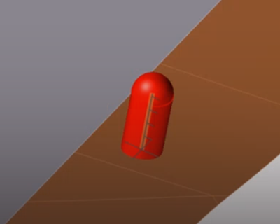
If a pin is positioned incorrectly inside the blank, click
the toggle to move the pin outside of the
blank.Figure 1. Incorrect pin position
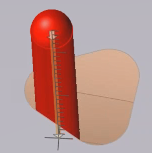
Figure 2. Correct pin position
Click to confirm the pin in the tool set.
The configuration of the pin is complete.
Note:
By default, the pin direction follows the draw direction of the
forming operation. If you change the draw direction, you have to
recreate the pins. The orientation of the pins does not change.
By default, the height of the pin is the distance from the tool
where the pin is attached to the blank at the selected
location.
If you place a pin inside of a hole, Inspire Form automatically
calculates a diameter for the pin. If the hole shape is irregular,
you can adjust the default value set by Inspire Form.
Add more pins
In the guide bar, select Pin. If you have already left
the context of the guide bar, click the existing Pin tool
from the tool set of the forming operation.
Repeat the tasks from Step 5 to configure the pin.
 button.
 A pin is added to the tool set.
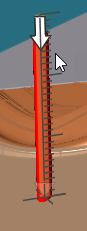
 toggle to adjust the pin inward or outward as
required.If a pin is positioned incorrectly inside the blank, click the
toggle to adjust the pin inward or outward as
required.If a pin is positioned incorrectly inside the blank, click the