Tutorial 2: Piping System
This exercise will walk the user through building a portion of the water circuit of a piping system. The user will learn how to:
- Edit chamber properties
- Edit element properties
- Check the model
- Run the model
- Post-process the model
- Chamber Types: Plenum, Momentum
- Element Types: Junctions, Incompressible Tube, Bends, Transition, Nozzle
- Fluid: Liquid Water
Step 1: Examine geometry and create plan
- The user will be creating a model of a water piping circuit shown in figure 1.01.
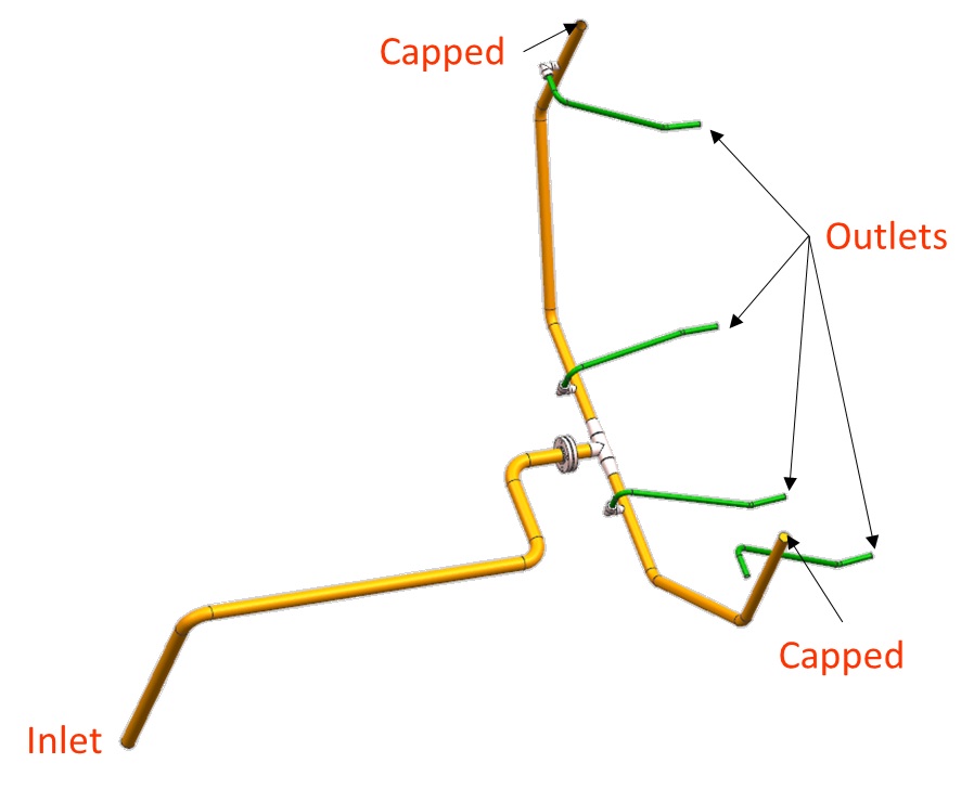
Figure 1.01: Water piping system
- The model begins with long runs of straight piping connected by 90-degree bends. It then splits in two directions and transitions into smaller diameter pipes, which then feed four spray nozzles.
- To model this piping system, the user will primarily be making use of tube, bend, and junction elements.
Step 2: Load IGES file
- Go to File → Load IGES File
- Browse to IGES location and select open (water_piping.igs)
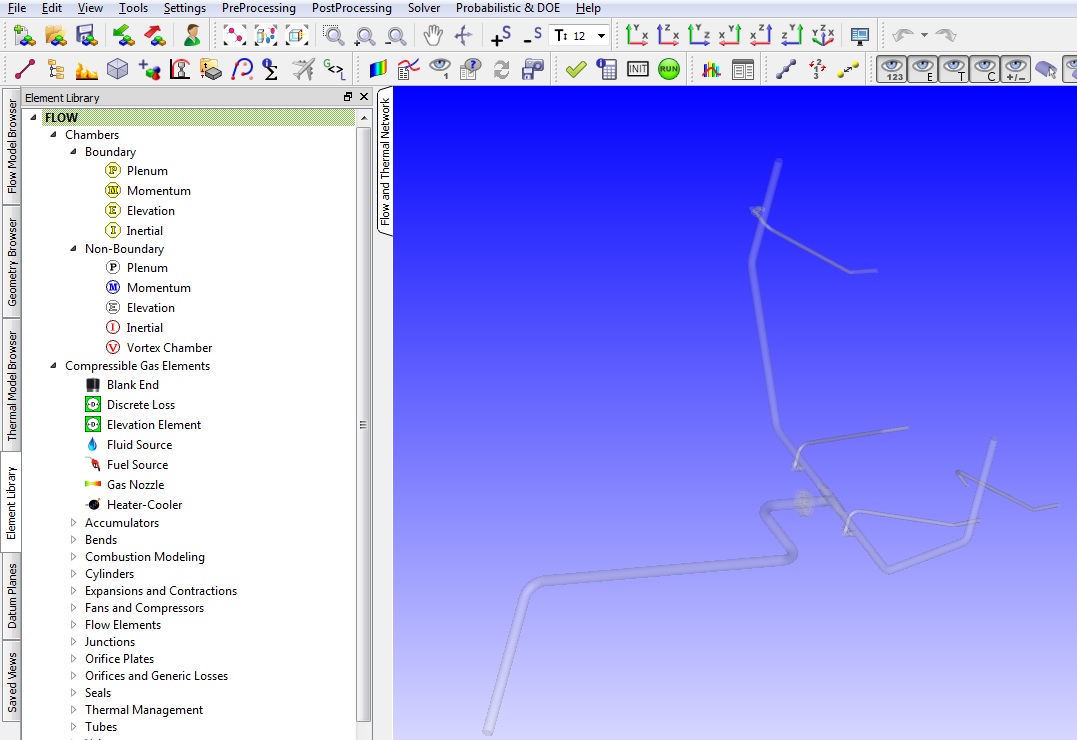
Figure 1.02: Loaded IGES on default background
Step 3: Building Model
- Plan model setup based on what is known about the geometry
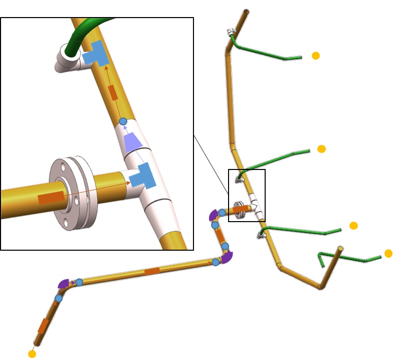
Figure 1.03: Sketch/Outline of model
- Drag and drop Boundary Plenum chambers at the inlet and outlet locations from Figure
1.01
- Pressing and holding “Shift” while dragging chambers and elements enables snapping to IGES vertices for easier placement (Figure 1.04)
- Additionally the translate (right click chamber/element → translate) option and manually editing the coordinates (Property Editor → Location), can be used to assist in placing chambers and elements in the right location
- Use
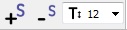 to adjust symbol and text size
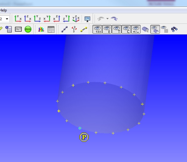
Figure 1.04: Snapping to IGES vertices
- Click and drag non boundary momentum chambers to the locations (blue circles) in Figure 1.03
- Set the inlet Plenum to a Static Pressure of 24.7 psi and Relative Total Temperature
of 70 F
- Set “Fluid Type” to “Single Liquid Species” and select “Water (L)” under “Single Liquid Species”
- Set the outlet Plenums to a Static Pressure of 14.7 psi and Relative Total
Temperature of 70 F
- Set “Fluid Type” to “Single Liquid Species” and select “Water (L)” under “Single Liquid Species”
- Click and drag Incompressible T-Junction elements to the pipe connection locations in Figure 1.05
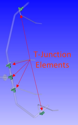
Figure 1.05: T-Junction element locations
- For the piping leading up to the T-connection, use Incompressible Tube elements to connect the straight sections of pipe and incompressible Standard Circular Bend elements for the bends as shown in Figure 1.03
- For the tube elements, use the lengths shown in Figure 1.06.
- Set the number of stations to 10, check “Specified Diameter” under “Cross-Section Shape” and input a diameter of 2.07 in
- Under Segment Data, set Roughness to 0.0018 in and check “Adiabatic” for “Station Heat Transfer”
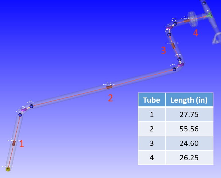
Figure 1.06: Tube Element locations
- For the Bend elements, set Bend Angle to 90 degrees, Bend Radius to 3.105 in, Diameter to 2.07 in, and Roughness to 0.0018 in
- After the T-Junction, place an Incompressible Conical Transition element, an Incompressible Tube element, followed by another Incompressible T-Junction as shown in Figure 1.07
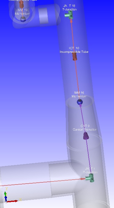
Figure 1.07: Post T-Junction model set-up
- For the Conical Transition Element set Contraction K Loss to 0.06, Length to 0.166 in, Inlet Diameter to 2.07 in, and Exit Diameter to 1.5 in
- For the T-Junction Element set “Angle Between Arm 1 & 2” to 90 degrees, “Through Pipe Diameter” to 2.07 in, and “Branch Diameter” to 2.07 in
- For the Incompressible Tube element set Length to 6.10 in
- Set the number of stations to 10, check “Specified Diameter” under “Cross-Section Shape” and input a diameter of 1.5 in
- Under Segment Data, set Roughness to 0.0018 in and check “Adiabatic” for “Station Heat Transfer”
- Plan to set up the spray nozzle as shown in Figure 1.08
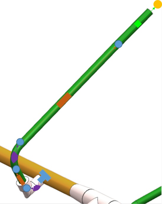
Figure 1.08: Nozzle model set-up
- Place the momentum chambers (blue circles) and connect them with Tube, Bend, and Liquid Nozzle elements as shown on figure 1.08
- For the first Bend Element use an incompressible Circular Mitre subtype and set Bend Angle to 90 degrees, Diameter to 0.81 in, and Roughness to 0.0018 in
- For the first Incompressible Tube element set Length to 4.32 in
- Set the number of stations to 10, check “Specified Diameter” under “Cross-Section Shape” and input a diameter of 0.81 in
- Under Segment Data, set Roughness to 0.0018 in and check “Adiabatic” for “Station Heat Transfer”
- For the second Bend element use a Incompressible Standard Circular subtype and set Bend Angle to 90 degrees, Bend Radius to 1.215 in, Diameter to 0.81in, and Roughness to 0.0018 in
- For the second Incompressible Tube element set Length to 30 in
- Set the number of stations to 10, check “Specified Diameter” under “Cross-Section Shape” and input a diameter of 0.81 in
- Under Segment Data, set Roughness to 0.0018 in and check “Adiabatic” for “Station Heat Transfer”
- For the last element in the spray nozzle, click and drag an Incompressible Liquid
Nozzle element
- Set Flow Number to 678
- Set Reference Specific Gravity to 1
- For the T-Junction Element set “Angle Between Arm 1 & 2” to 90 degrees, “Through Pipe Diameter” to 1.5 in, and “Branch Diameter” to 0.81 in
- At this point, since this is a symmetrical mode, it is possible to copy and paste
the elements, along with their inputs, from one side of the model to the other
(Figure 1.09)
- One method of doing this is by copying an entire branch of chambers and elements using “Shift” to select multiple entities and “Ctrl+C” and click at the desired location to copy and paste, followed by the use of rotate and translate to align with the IGES
- Additionally, placing momentum chambers and then individually copying elements one at a time is also an option (this may be easier to align with the IGES)
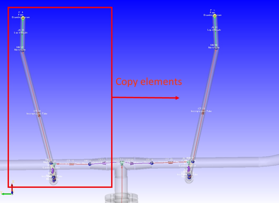
Figure 1.09: Copying elements with inputs due to model symmetry
- Set up the remaining portion of the tubing as shown in Figure 1.10
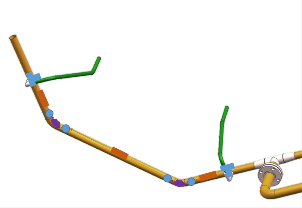
Figure 1.10: Remaining piping set-up
- Place momentum chambers as shown (blue circles) in Figure 1.10 and connect them with Tube and Bend elements
- Place Incompressible Tube elements at the straight pipe locations. For the long tube
use a length of 36.36 in and for the two shorter tubes use a length of 14.15 in
- Set the number of stations to 10, check “Specified Diameter” under “Cross-Section Shape” and input a diameter of 1.5 in
- Under Segment Data, set Roughness to 0.0018 in and check “Adiabatic” for “Station Heat Transfer”
- Place Incompressible Standard Circular Bend elements at the bends and set Bend Angle to 90 degrees, Bend Radius to 4 in, Diameter to 1.5 in, and Roughness to 0.0018 in
- Copy and paste the new elements, along with their inputs, from one side of the model to the other (Figure 1.11)
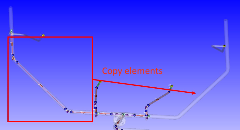
Figure 1.11: Copy new elements to other side of model
- Use the existing spray nozzle set-up to copy and paste the elements, along with their inputs to the remaining nozzles (Figure 1.12) and connect them to the T-Junction elements created earlier

Figure 1.12: Copy existing spray nozzle set-up
- To cap the model, drag and drop a boundary plenum at both non-nozzle ends, and use a
“Blank End” element to connect the plenum to the T-Junction element as shown on
Figure 1.13
- Set boundary plenums the same as the other outlet plenums
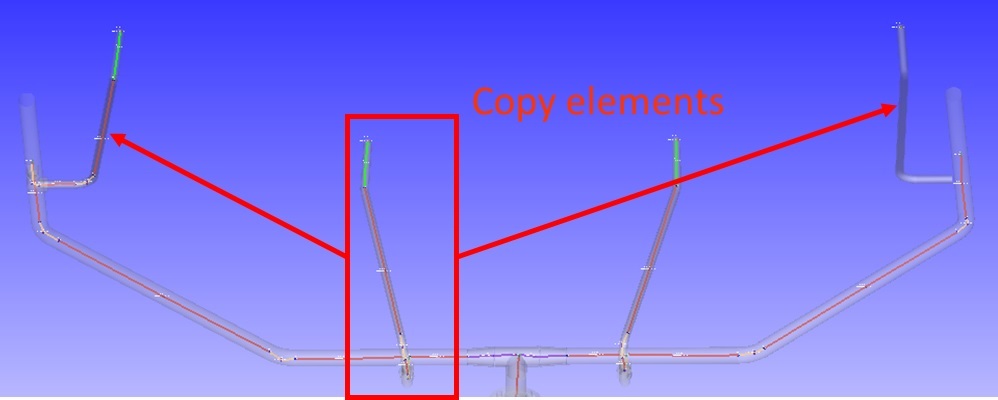
Figure 1.13: Use Blank End Element to cap model
- Go to Solver → Analysis Setup →Working Fluid and set “Fluid Properties Option” to
“30: All Water (L)”
- This tells the model to use water as the fluid in the system
Step 4: Check Model and Run
- Select checkmark icon from the top toolbar
 to check the model for warnings/errors.
- An error should populate stating that the internal chamber has not been initialized
- Select the initialization icon from the toolbar
 , and pick Start. Accept values once flow solver has
converged.
, and pick Start. Accept values once flow solver has
converged. - Select run icon from toolbar
 . Run Flow Simulator.
Step 5: Post-process
- Results file (*.res) should automatically be loaded into GUI. If not, it can be selected via File → Load Result File
- By default, both chamber and elemental results are displayed in the graphical workspace.
- Customization of the displayed results is accessible within Settings → Display
Options
- Display the flow in GPM and the static pressure.
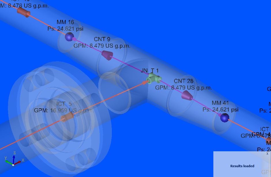
Figure 1.14: GPM and Static Pressure near Junction 1