Face Recognition Settings
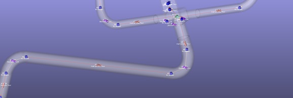
Flow Simulator inserts some of the elements automatically based on face recognizing algorithm. Users should specify Element’s Flow Equation type, geometry tolerances, and roughness before selecting faces.
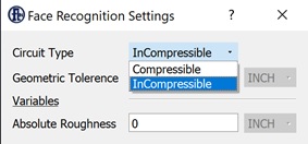
Circuit Type: specifies from which library the elements will be selected. Based on the user selection, the elements will use either compressible or incompressible equations in the flow calculations.
Geometric Tolerance: users should provide tolerance between the faces so that the algorithm can decide whether to insert one element or divide the face into two elements.
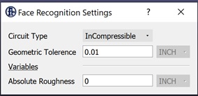
Absolute Roughness: Flow Simulator adds roughness in the friction calculations if users provide. This section will add same roughness value for the elements that are automatically inserted through face recognition algorithm.
Additional Items
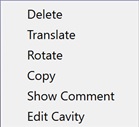
These options are available on Right Clicking on FlowSimulator Model window.
Selectable IGES:
This operation enables users to select the CAD model and perform Delete, Translate, Rotate, Copy, Show Comment and Edit Cavity operations.
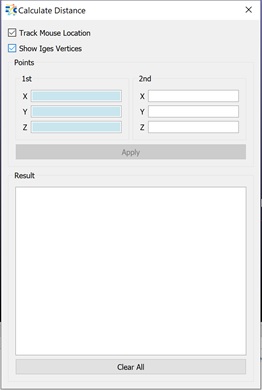
Enable/Disable Vertices
If there are vertices on the CAD model, this function enables/disables to see these vertices, otherwise the vertices will be hidden all the time and will be showed only when the users select “Measure Distance” operation.
Enable Edge Selection
Flow Simulator enables users to select the edges of the CAD geometry and insert Vertices on the lines, arcs. The available options are;
Insert Vertex: add vertex at the mouse click location
Distribute Vertices distributes the vertices on the selected line based on vertex number or the distance between the vertices.
Insert Vertex mid of arc: add a vertex at the middle location of the arc.
Insert Vertex on middle: add a vertex at the middle location of the line.
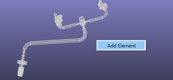
Enable Face Selection
In order to insert elements based on the face recognition functionality, users first need to enable Face selection option, and select the faces;
- Single selection
- Shift+single selection
- Box selection
Display IGES shape
Shows or hides the CAD model.