Add Time Variance to Objects
Time variance can only be used together with indoor databases (.idb), not with urban databases. Time variant properties can only be assigned to groups of objects.
The button ![]() is used to switch to the time variant mode.
Alternatively, the menu item can be used. Editing and saving is not possible in this mode. To further
edit or save the database, the user has to return to the ordinary mode first (by clicking
on Leave in the Time Control window).
is used to switch to the time variant mode.
Alternatively, the menu item can be used. Editing and saving is not possible in this mode. To further
edit or save the database, the user has to return to the ordinary mode first (by clicking
on Leave in the Time Control window).
The following table shows a comparison of both modes:
| Criterion | ALD Mode | RAC Mode |
|---|---|---|
| Definition of distance | Absolute distance. | Relative distance. |
| Duration of rotation | Duration of rotation defined by length of path. | Duration of rotation either defined by length of path or by rotation angle. |
| Orientation of rotation | Orientation of rotation defined by former direction of movement. | Orientation of rotation defined by user (clockwise / counter-clockwise). |
| Applications | Vehicles (for example, on streets, on rails) | Inside buildings (for example, doors, elevators) Automation (for example, robots) |
As shown in the table above, the two modes are designed for different applications. For scenarios with vehicles on streets or rails ALD mode should be preferred. For other time variant scenarios, the RAC mode is the best solution. Depending on the selection, the definition of transformation/rotation differs.
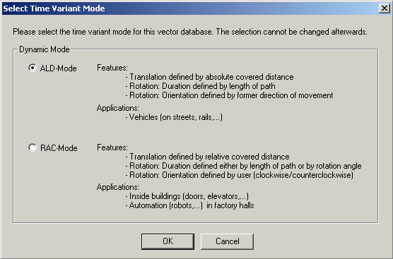
Figure 1. The Select Time Variant Mode dialog.
ALD Mode
- Translation
- This property moves an object along a direction vector. Thus, a direction vector has to be entered, as well as the velocity for the translation.
- Rotation
- This property rotates an object with respect to the selected rotation axis. The rotation center has to be defined, as well as the velocity.
The time variant transformations (translation and rotation) are defined with respect to the distance, the selected object has already covered. The definition of several transformation properties for one object with respect to different distances is of course possible. So it is possible to define arbitrary movements for all objects in the scenario.
| Case | Behaviour |
|---|---|
| Vn > Vn+1 | The object will have steady deceleration between the two time stamps. |
| Vn < Vn+1 | The object will have steady acceleration between the two time stamps. |
| Vn = Vn+1 | The object will have constant velocity between the two time stamps. |
RAC Mode
- Translation
- This property moves an object along a direction vector. Thus, a direction vector has to be entered, as well as the velocity for the translation.
- Rotation
- This property rotates an object with respect to the selected rotation axis. The rotation center has to be defined, as well as the velocity. The duration of the rotation is either defined in meters or in degrees.
The definitions of covered distance/angle are relative in RAC mode. The behaviour of acceleration and deceleration of objects differs also from the definition in ALD mode:
| Former Movement | Current Movement | Behaviour |
|---|---|---|
| Translation | Translation | The object accelerates or decelerates, if velocities of both points are different. |
| Translation | Rotation with respect to covered distance | The object accelerates or decelerates, if velocities of both points are different. |
| Translation | Rotation with respect to covered angle | The object moves with constant velocity until it reaches the point where the rotation starts. The velocity is then set to the angular velocity defined by the user. |
| Rotation with respect to covered distance | Translation | The object accelerates or decelerates, if velocities of both points are different. |
| Rotation with respect to covered angle | Translation | The object rotates with constant velocity until the object reaches the point, where the translation starts. The velocity is then set to the value in m/s defined by the user. |
Assignment of Time Variance
After the time variant mode was started, the user can assign time variant behavior to each object (group) in the current scenario. Therefore the group has to be selected in the dropdown box shown in Figure 2. In this screenshot, the group “Blue Car” is selected and its time variant behaviour is shown in the table.
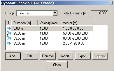
Figure 2. The Dynamic Behaviour (ALD-Mode) dialog.
| Translation | Defined by velocity and direction vector. | |
| Rotation around x-axis | Defined by velocity or angular velocity and rotation center. The direction of the rotation is determined automatically. | |
| Rotation around y-axis | Defined by velocity or angular velocity and rotation center. The direction of the rotation is determined automatically. | |
| Rotation around z-axis | Defined by velocity or angular velocity and rotation center. The direction of the rotation is determined automatically. | |
| Rotation around x-axis | Defined by velocity or angular velocity and rotation center. The direction of the rotation is manually defined (clockwise/counter clockwise). | |
| Rotation around y-axis | Defined by velocity or angular velocity and rotation center. The direction of the rotation is manually defined (clockwise/counter clockwise). | |
| Rotation around z-axis | Defined by velocity or angular velocity and rotation center. The direction of the rotation is manually defined (clockwise/counter clockwise). |
There are several buttons available to define the time variant behaviour for the selected object.
After pressing the button Add or Edit, a new window appears (see Figure 3) to define (resp. change) the time variant properties for the selected group. First of all the type of transformation must be selected with the radio buttons: Translation or rotation. Then the properties have to be entered. Depending on the mode (RAC or ALD), there may be different edit boxes visible on the dialog. By clicking OK, the changes will be applied.
With the buttons Import / Export, time variant behaviour of an object can be loaded/stored from/into a file. In RAC mode, the data is stored in .rac files, in the ALD mode, the data will be written to .ald files.
Figure 3. The Add Transformation dialog.
The dialog window Time Control (see Figure 4) is always opened in the time variant mode. If it is closed by the user, the time variant mode is closed and WallMan returns to the ordinary edit mode. The time variant properties are not lost, they are stored in the database.
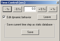
Figure 4. The Time Control (sec) dialog.
Several buttons are offered in the Time Control dialog to change the current time. With the buttons –1s and –0.1s, the current time is decreased and with the buttons +0.1s and +1s, the time is increased. The following hotkeys are also available to change the time:
| Hotkey | |
|---|---|
| Page Up | Time +0.1s |
| Page Down | Time –0.1s |
| Ctrl+Page Up | Time +1.0s |
| Ctrl+Page Up | Time –1.0s |
The Edit properties check box is used to open or close the window Dynamic Behaviour. When the user presses the Leave button, WallMan returns to the ordinary edit mode.
As an alternative, trajectories can also be used for the definition of time variant movements. This is often more convenient than using the dialog of Figure 2. Trajectories can be drawn with the corresponding paint tool by selecting . The polylines are displayed with orange lines in WallMan.
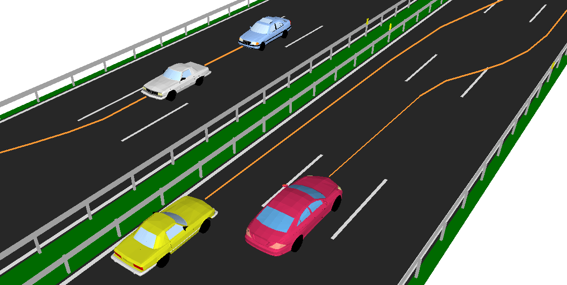
Figure 5. Trajectories in WallMan
The assignment of a trajectory to an object (group) can be done with the dialog of Figure 2. By clicking Trajectory, you can select one of the trajectories drawn before.
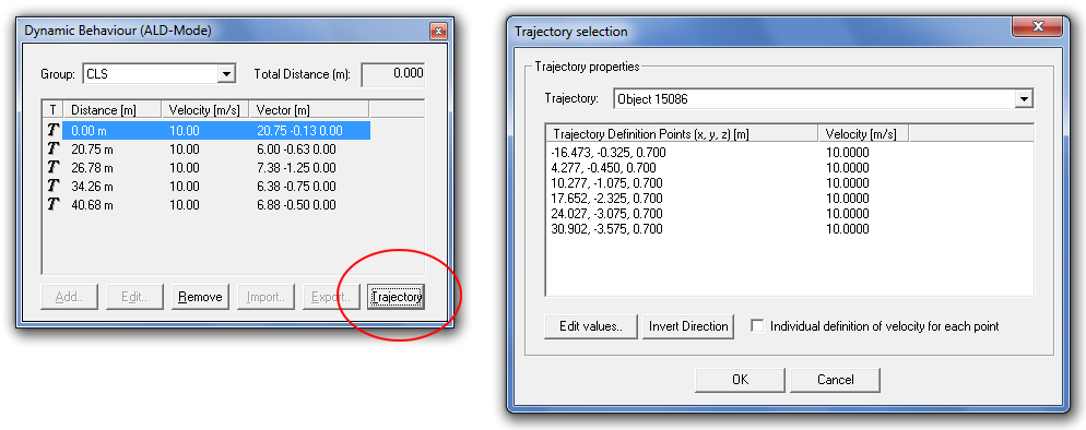
Figure 6. Selection of a trajectory for an object / group.
In the trajectory selection dialog the time variant behaviour can be defined for the selected trajectory. It is possible to define one velocity for the complete polyline or an individual velocity for each section of the polyline. The definition is automatically added to the table with the time variant information and indicated by a T. This means that the values cannot be modified manually, as the trajectory mode is used. The link to the trajectory can be removed by clicking Remove.