TDMA
Air Interface Parameters
For time division multiple access the following settings are available:
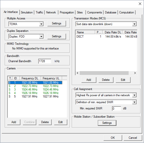
Figure 1. The Edit Project Parameters dialog, Air interface tab.
- Multiple Access Settings
-
The number of time slots on a carrier as well as the maximum number of time slots for a single radio link can be specified on the TDMA properties dialog by clicking the Settings button on the Air Interface tab.
The power back off used for cell assignment can be specified here as well. This back off specifies the attenuation of the pilot signals and is defined with respect to the maximum available transmit power of the corresponding carrier.
Note: As the signals used for cell assignment are transmitted in a separate time slot, this back off value does not influence the available transmit power for data transmission.
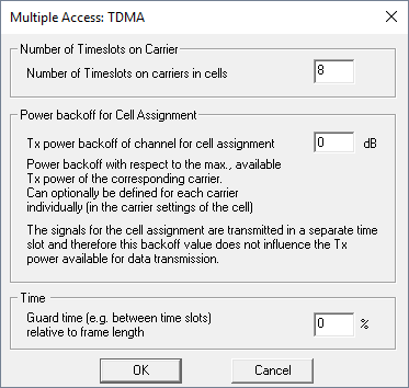
Figure 2. The Multiple Access: TDMA dialog.
- Duplex Separation
- Separation of uplink and downlink is in frequency (frequency division duplex). Further settings related to the duplex separation can be specified by clicking on the Settings button.
- MIMO Technology
- MIMO technology is not supported for this air interface.
- Channel Bandwidth
- Available bandwidth of the channel. This value is used to calculate thermal noise impact.
- Carrier Separation
- Frequency separation of two adjacent carriers. This value is used for determination of adjacent or co-channel interference.
Output Options
- General Results
- Best Server (Cell Assignment)
- Maximum achievable Throughput
- This results describes the overall throughput which is possible considering the defined network with various transmission modes and possibly multiple carriers.
- EMC Analysis
- Individual Results for each Modulation and Coding Scheme
- Minimum Required Transmitter Power
- Maximum achievable Received Signal Strength
- Reception Probability (including Fast Fading)
- SNIR (Maximum achievable SNIR)
- Maximum Number of Parallel Streams at Pixel
- This result describes how many streams can be supported in parallel at the given location (with respect to the defined transmission mode and the overall number of available time slots).
- Throughput at Pixel in Transmission Mode
- This result describes the maximum throughput at the given location evaluating the data rate of the defined transmission mode and the maximum number of parallel streams.
- Results Related to the Cell Assignment
- Serving Carrier: Received Power (Cell Assignment)
- Serving Carrier: SNIR (Cell Assignment)
- Number of Carriers Received
- Number of TRX Received
- Number of Sites Received
- Neighbor Cell List
- Analysis of the Serving Carrier
- Serving Carrier: Received Signal, Noise + Interference
- Serving Carrier: Received Noise + Interference