OFDM / SOFDMA (Downlink and Uplink)
Orthogonal frequency division multiple access is a multiple access scheme, used in nearly all actual and future wireless air interfaces, such as DVB-T/DVB-H, DAB, LTE, WiMAX, WLAN and 5G.
A large number of closely-spaced orthogonal subcarriers are used to carry data. The data is divided into several parallel channels, one for each subcarrier. Each subcarrier is modulated with a conventional modulation scheme (such as QAM or QPSK) at a low symbol rate, maintaining total data rates similar to conventional single-carrier modulation schemes in the same bandwidth.
Air Interface Parameters
All parameters related with a selected air interface can be specified on the Air Interface tab of the Edit Project Parameter dialog. For orthogonal frequency division multiple access, the following settings are available:
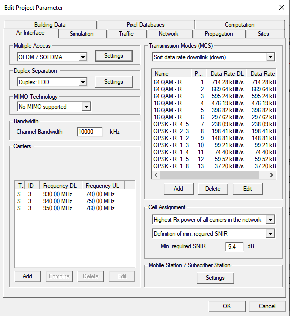
Figure 1. The Edit Project Parameters dialog, Air interface tab.
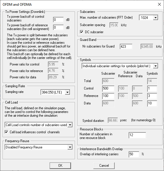
Figure 2. The OFDM and OFDMA dialog.
- Multiple Access Settings
Settings related to the multiple access mode (guard period, sub-channelization) can be specified in the dialog shown below, which is reachable by pressing the corresponding Settings button on the Air Interface tab.
- Tx Power Settings (Downlink)
- The Tx power is split among the given sub carriers (by default each sub carrier gets the same power). In case the sub carriers with pilot or reference signals should get less power an additional backoff can be defined. The resulting shares of the Tx power for the transmission of pilot, reference and data signals are displayed here, which are computed by evaluation of the settings defined in the field “Symbols”.
- Sampling Rate
- Cell Load
- The cell load can be used to either control the “Tx power in downlink” or the “Number of sub carriers used”. If the option “cell load controls Tx power in downlink” is selected the power is adapted on all data sub carriers in the same way which leads to the same interference situation on all data sub carriers (for example in case of 50% load every data sub carrier gets 3 dB less than the maximum power per sub carrier). If the option “cell load controls number of subcarriers used” is selected, the sub carriers are transmitted either with the maximum power per sub carrier or the sub carriers are not transmitted at all (for example in case of 50% load only every second data sub carrier is used in the considered cell, which means that the other 50% of the sub carriers can be used without interference in the neighboring cells).
- Frequency Reuse
- Sub Carriers
- Maximum number of sub carriers used, thus the size of Fast Fourier
Transformation.
Number of guard and pilot sub carriers. The number of data sub carriers depends on the other parameters specified and is calculated automatically.
- DC sub carrier
Sub carrier spacing and symbol duration are calculated automatically based on the specified system parameters. Depending on the channel bandwidth and the numerology, a certain total number of subcarriers will be available. This number has been set by the 3GPP (www.3gpp.org). Of those many subcarriers, most are used to transmit data, but some are needed to send reference signals, send control signals or provide a guard band.
- Maximum number of sub carriers used, thus the size of Fast Fourier
Transformation.
- Guard Band
- Symbols
- This field allows to define the split of the resources (symbols and sub carriers) among the different signal types (pilot, reference, and data). If “identical settings for each symbol” is selected the split can be only done in the frequency domain by defining a corresponding number of sub carriers for pilot and reference signals (the remaining sub carriers are used for data transmission). If the option “individual sub carrier settings for symbols (pilot./ref.)” is selected a more detailed assignment of the resources in both the time and frequency domain is possible, which is especially important for LTE networks as it effects the power and interference situation for the reference signals (RSRP, RSRQ, RSSI).
- Figure 3
shows the split among data, pilot and reference signals in a LTE physical
resource block (for the symbols which carry the reference signal). This
resource assignment for LTE is defined under
Symbols, see Figure 2.
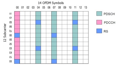
Figure 3. The split among data, pilot and reference signals in a LTE physical resource block.
- Resource Blocks
- In this field the number of sub carriers in one resource block can be defined. The option “fractional load allowed” is only relevant if the option “cell load controls number of subcarriers used” is selected. In case the transmission modes include the transmission of a certain number of resource blocks in parallel (for example, 25 in case of 5 MHz bandwidth) the activation of this option evaluates the situation on higher granularity (resource block level), thus how many resource blocks can be transmitted in parallel (especially if below the defined number in the transmission mode).
- Interference Bandwidth Overlap
-
In network planning simulations in ProMan, two antennas interfere if they are on the same frequency. If two antennas are not on the same frequency, their interference is negligible. For modern wireless standards that use OFDM/SOFDMA, such as LTE and 5G, the situation is slightly more complicated. Each carrier may have hundreds of subcarriers. You select for each base station antenna on which carrier it operates, but the simulation does not select the precise subcarriers.
This parameter enables you to specify to what extent the subcarriers, used by different antennas, may overlap and interfere. The best case is 0%, which is approximated when traffic is low, while the worst case is 100%, which may occur in high traffic.
-
- Tx Power Settings (Downlink)
- Duplex Separation
- Separation of uplink and downlink in cellular networks can be chosen to be either in frequency (frequency division duplex) or in time (time division duplex). Besides this, simplex mode can be chosen for broadcasting applications (downlink only). Further settings related to the duplex separation can be specified by clicking on Settings.
- MIMO Technology
- MIMO technology can be either disabled or enabled using two or four parallel streams.
- Channel Bandwidth
- Total bandwidth of the channel. This value is used to calculate the sub carrier spacing. Based on the spacing and the number of sub carriers for a certain transmission mode the thermal noise is determined.
- Carrier Separation
- Frequency separation of two adjacent carriers. This value is used for determination of adjacent or co-channel interference.
Output Options
- General Results
- Best Server (Cell Assignment)
- Maximum achievable Throughput
- This results describes the overall throughput which is possible considering the defined network with various transmission modes and possibly multiple carriers.
- EMC Analysis
- Individual Results for each Modulation and Coding Scheme
- Minimum Required Transmitter Power (BS) in downlink (output power of PA)
- Minimum Required Transmitter Power (MS) in uplink (output power of PA)
- Maximum Received Power (MS) in downlink (considering number of streams)
- Maximum Received Power (BS) in uplink (considering number of streams)
- Reception Probability (including Fast Fading)
- SNIR (Maximum achievable SNIR)
- Maximum Number of Parallel Streams at Pixel
- This result describes how many streams can be supported in parallel at the given location (with respect to the defined transmission mode and the overall number of available resource blocks).
- Throughput at Pixel in Transmission Mode
- This result describes the maximum throughput at the given location evaluating the data rate of the defined transmission mode and the maximum number of parallel streams.
- Results related to the cell assignment
- Serving Carrier: Received Power (Cell Assignment)
- Serving Carrier: SNIR (Cell Assignment)
- Pilot: Total received (signal + noise + interference)
- Considers the bandwidth of the pilot/reference signals.
- Pilot: Interference level (noise + interference)
- Considers the bandwidth of the pilot/reference signals.
- Results related to the cell assignment
-
- Serving Carrier: Received Power (Cell Assignment)
- Serving Carrier: SNIR (Cell Assignment)
- Pilot: Total received (signal + noise + interference)
- Considers the bandwidth of the pilot/reference signals.
- Pilot: Interference level (noise + interference)
- Considers the bandwidth of the pilot/reference signals.
- LTE Reference Signals (RSRP, RSSI, RSRQ)
- Reference Signal Received Power (RSRP) is the average of the power measured in a single resource element that contains cell-specific reference signals. RSSI is the total received wideband power on the given frequency bandwidth, which includes the power from the own cell and from interfering cells as well as any other noise source. Reference Signal Received Quality (RSRQ) is the difference between RSRP and RSSI considering the number of resource blocks: RSRQ = 10.0*log(# of RB) + RSRP - RSSI.
- Number of Carriers Received
- Number of TRX Received
- Number of Sites Received
- Neighbor Cell List