Compute indoor propagation using Fresnel coefficients.
Model type
The propagation project is for an indoor scenario for a single-story building. The
simulation is done for only a single prediction height at 1.5 m above the
ground.
Sites and Antennas
There is only one omnidirectional transmitter, situated at a height of 2 m and
operating at 2 GHz.
Tip: Click Project > Edit Project Parameter and click the Sites tab to view the
transmitter details.
Computational Method
This project uses standard ray tracing without a preprocessed database.
Tip: Click Project > Edit Project Parameter and click the Computation tab to change
the model.
In this part of the example, the simulation uses Fresnel equations for the
determination of the reflection and transmission loss and the GTD/UTD (geometrical
theory of diffraction / uniform theory of diffraction) for the determination of the
diffraction loss The model uses four physical material parameters:
thickness
permittivity
permeability
conductivity
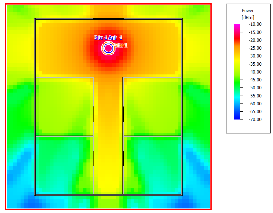
Results
Propagation results show, at every location, the power received from the transmitting
antenna. The results are shown for a prediction plane at a height of 1.5 m from the
floor.
Figure 1. Received power for the Fresnel coefficients.