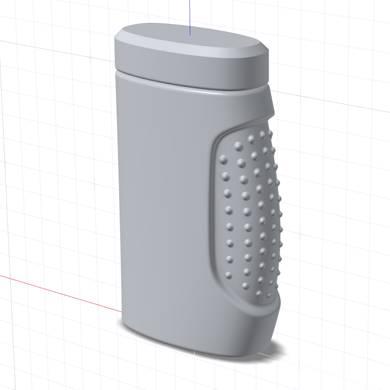
Tutorial: Basic Surfacing 2

Continue to learn basic surfacing techniques by building on the same model from the first basic surfacing tutorial. In this follow-up tutorial, you will continue modifying the model by using tools like Combine, Shelling, Section Cut, Tolerance Check, Extract Isoparms, Replicate, and Round.

In this lesson you will learn about:
  • Combine
  • Shelling
  • Section Cut
  • Tolerance Check
  • Extract Isoparms
  • Replicate
  • Round


Create the Bottle Opening

  1. Open the file saved at the end of the first basic surfacing tutorial.
  2. In the Model Browser, copy and paste the top circle used to create the main loft surface.
  3. Exit the Move tool.
  4. Double-click to edit the circle and select all points.
    Tip: It is easier to double-click the circle in the Model Browser.
  5. In the guide bar, click Unedit Selected.
  6. The circle is returned to its default shape.
  7. Change the diameter to 2 cm.

Combine Surfaces and Boolean

Combine can be used to stitch surfaces with shared edges (at least positional continuity). If the input surfaces form a closed space, the result of a Combine operation is a solid body.
  1. On the Modify tab, select the Combine tool.

  2. Press V to turn on the Select Surfaces filter.
  3. Box select all of the surfaces.
  4. Right-click and mouse through the check mark to exit, or double-right-click.
  5. Press V again to turn off the Select Surfaces filter.
    Tip: An alternate is to press Q to hide all curves in Step 2 above. Remember to toggle Q off to show the curves, since any new curves created will be automatically hidden after creation.
    Tip: It is good practice to check for open edges at this point.
  6. On the Analysis tab, select the Tolerance Check tool.

  7. Select the Combine object. Right-click to confirm.
  8. In the Control Panel, the Result of the tolerance check should say Closed solid.
  9. Using the Extrude tool, extrude the circle created in Step 1 by 1.25 cm.
  10. In the Control Panel, turn on Draft 1 and enter a value of 2 for the Draft 1 angle.
  11. Turn on Caps.
  12. On the Modify tab, in the Booleans tool group, select the Union tool.

  13. Select the Combine and Extrude as input objects. Right-click to confirm.
  14. Right-click and mouse through the check mark to exit, or double-right-click.
  15. Save the file.

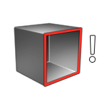
Shelling and Section Cuts

  1. On the Modify tab, select the Shelling tool.

  2. Select the top face of the Extrude as the shell face.
  3. Enter a value of 1.25 cm as Global Thickness. Right-click to confirm.
    We can check the shelling operation using the Section Cuts tool.

    The Shelling tool allows you to choose custom thickness for certain faces.

  4. Double-click to edit the shell object.
  5. In the Control Panel, turn on Custom Mode.
  6. Select the bottom face.
  7. Enter a value of 0.3 cm for Custom.
  8. Right-click and mouse through the check mark to exit, or double-right-click.

Create the Cap

  1. Extrude the top circle of the loft body by 1.5 cm with Caps and Thickening.
  2. Use the on graphic manipulator to remove the cap on the bottom face.
  3. Click the check mark to complete this step.
  4. Isolate the extrude object.
  5. On the Modify tab, select the Offset (surface) tool.

  6. Select the extrude as input. Right-click to confirm.
  7. Enter 0.25 cm as the Global Offset.
  8. In the Control Panel, turn on Custom Mode and click the inner wall of the cap.
  9. Edit the offset distance to 0.125 cm.
  10. Right-click and mouse through the check mark to exit, or double-right-click.

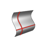
Create the Grip Surface

  1. On the Curves tab, select the Extract Isoparms tool.

  2. Click the indented surface as input.
  3. Hover the mouse over the surface to see a preview of the isoparm.
  4. Click to extract.
    In this case, a total of 4 isoparms are extracted.
  5. Right-click and mouse through the check mark to exit, or double-right-click.
  6. Double-click the extract curve to edit its location precisely.
  7. Create a sphere of about 0.2 cm.
  8. Using Replicate, select the sphere as the input and the first isoparm as the path.
  9. Use the Start U and End U options of Replicate to edit coverage of the replicates.
  10. Click the Advanced tab and turn on Scaling transformation. Use 0.75 for X, Y, and Z.
  11. Finally, enable Combined Output in the guide bar of the replicate and click the green check mark to complete.
    Repeat the above steps for the remaining isoparms.

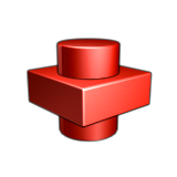
Symmetry and Boolean

  1. On the Modify tab, select the Planar Symmetry tool.

  2. Select the 3 replicates, leaving out the one in the center.
  3. Use Y as the mirror axis.
  4. Edit the axis origin to 0, 0, 0.
  5. Enable Combine with inputs.
  6. Close the tool.
    At this point, you can modify the replicate source (the sphere) to adjust the size.
    Using the Boolean Union tool on the Modify tab, select the replicates and the main body as inputs.

Round

The Round tool allows you to add multiple edge sets of different round types, making it one of the most powerful tools in Inspire Studio.

  1. Select the Round tool and box select the spheres on the grip surface. Right-click to confirm edges.
  2. Edit the round radius to 0.1 cm.
  3. Click Add Edge set, switch to Wireframe mode (press 1), and select the inner edge of the bottom surface. Add a radius of 0.2 cm.
  4. Right-click to confirm.
  5. Click Add edge set again.
  6. Select the bottom outer edge and top outer edge and set a radius of 0.2 cm.
  7. Add two edge sets for the cap, one with a chamfer of 0.3 cm for the top edge and 0.125 cm for the bottom edge.
  8. Save the file.