Tutorial: Loft Addendum
Learn to build addendum surfaces using the Loft addendum tool.
In this lesson, you will learn about:
- Adjusting the draw direction while performing a draft analysis
- Creating the addendum and tweaking the shape by copying a rib
Change the Default Units
In Inspire Studio, the default unit of measurement is centimeters and grams. In this tutorial, we'll be using millimeters and kilograms.
Import the File
First, download and unzip this file: bpillar_mod_w_mod_binder.zip.
-
Browse to the bpillar_mod_w_mod_binder.x_b file.
The model is loaded.
Define the Part
Select a part and define the thickness and position.
-
Click the Part icon.
-
Click the Assign icon.
-
Select the part, shown below in yellow.
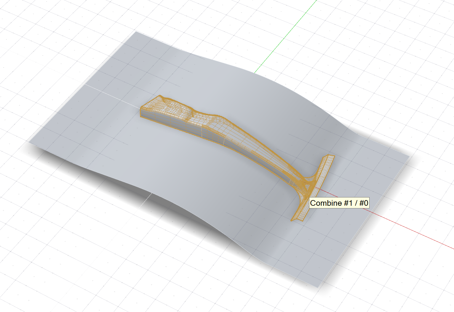
Note: Red dots indicate discontinuity vertices (locations where edge discontinuity occurs) or corners. Ribs will be automatically added here when you create the addendum.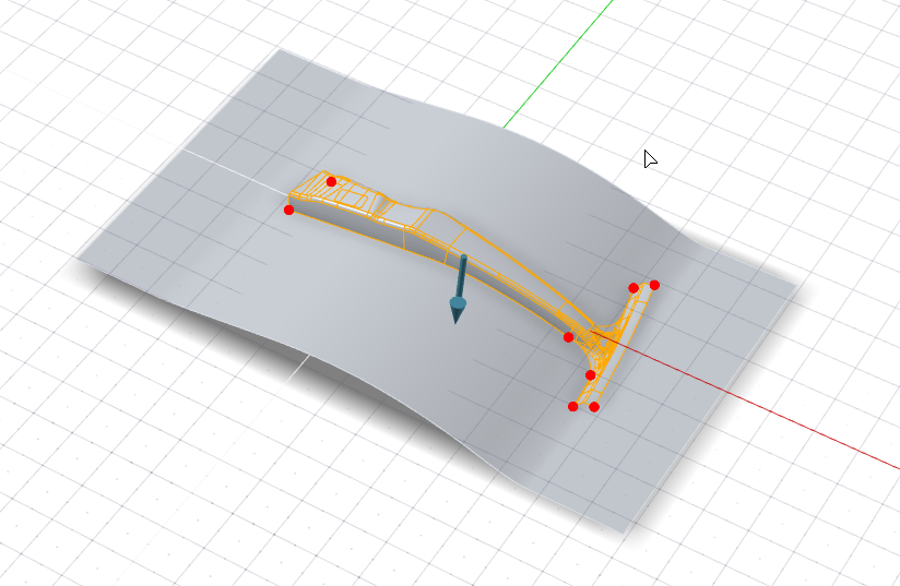
-
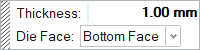
By default, the part is designated as the Bottom Face of
the thin solid. In this tutorial, we'll keep the default setting.
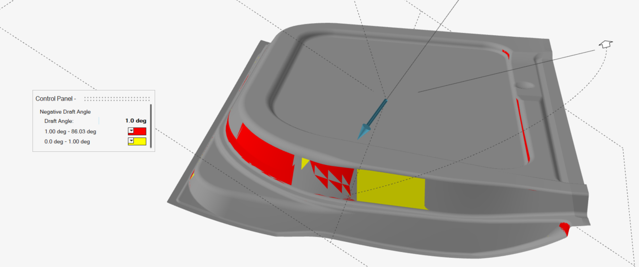
Set the Draw Direction
Adjust the draw direction to minimize the depth and avoid negative drafts with the help of the Depth Box and Draft Analysis.
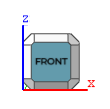
On the View Cube, click Front to
rotate the model to the front view.
-
Click the Draw Direction icon.
-
To display the draw depth, in the guide bar, select Depth
Box.

-
To display severe negative drafts in red and marginal negative drafts in
yellow, select Draft Analysis.
-
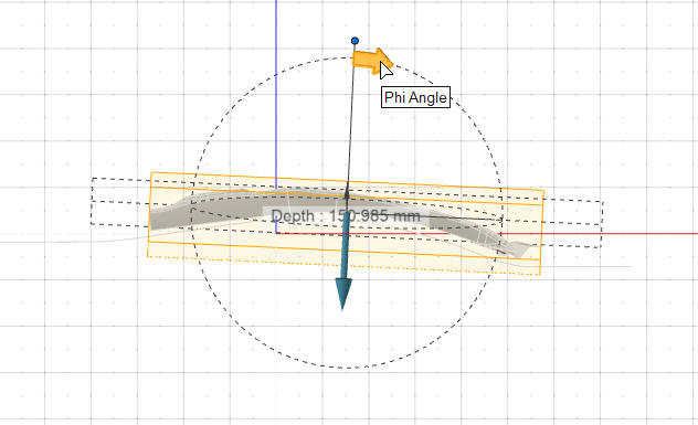
Set the draw direction:
-
Click the Phi Angle arrow.
-
Enter an angle of 5.0 deg.
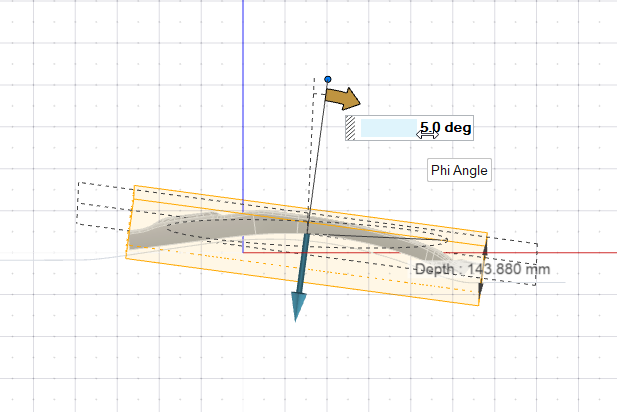
-
Click the Phi Angle arrow.
- Right-click and mouse through the check mark to exit, or double-right-click.
Create the Binder
Define a binder for the draw die. In this tutorial, we'll assign an existing surface as the binder.
Rotate the model to return to the 3D view.
-
Click the Binder icon.
-
Click the Assign icon.
-
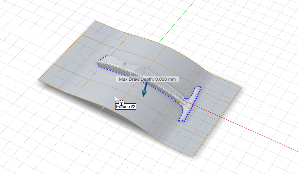
Selectable edges are green. Click one of these addendum start edges.
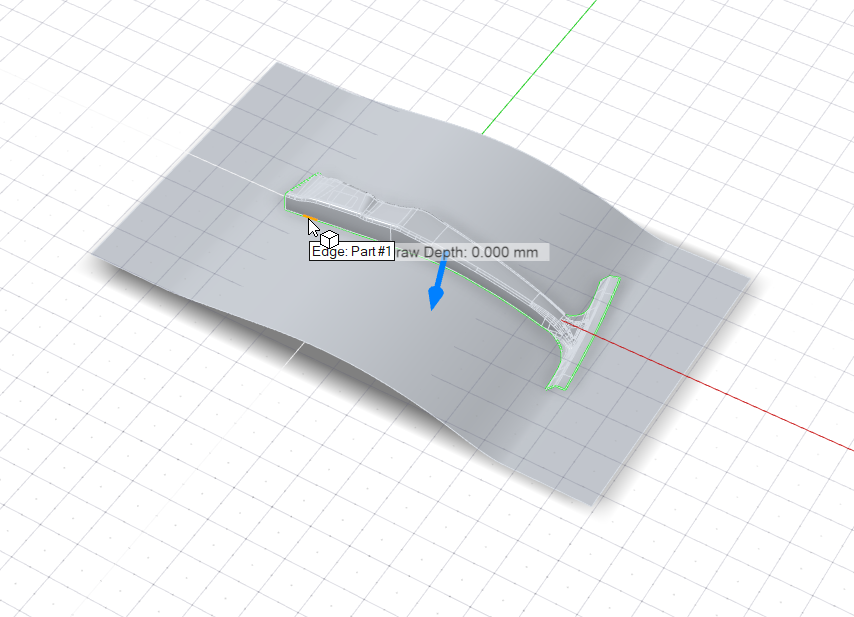
Because Chain selection is the default selection method, all connected edges are selected automatically and now displayed in dark blue.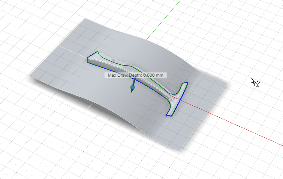 Note: By default, the Max Draw Depth (the maximum distance between the part and binder) is displayed.
 -
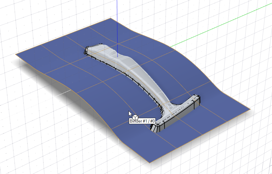
Assign the binder:
- In the guide bar, select Binder.
- Select the surface (Extrude #2), outlined in yellow below.
Create the Addendum
After creating the addendum, we'll tweak the shape by copying a rib.
-
Click the Addendum icon.
-
Click the Loft icon.
-
Select the start edges of the addendum. Selectable edges are green.
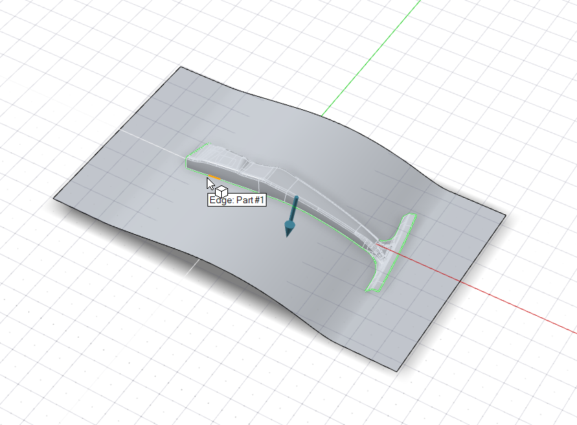
Note: The binder for the addendum is implicitly assigned from the selected edges. -
To select where you want to automatically create ribs, in the Control Panel,
for Auto create rib locations, select All
Vertices. Ribs will be automatically created at all vertices,
points, and locations on the part edge. This includes vertices on the edge,
T-intersection vertices, and discontinuity vertices.
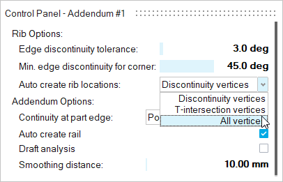
All vertices are now selected.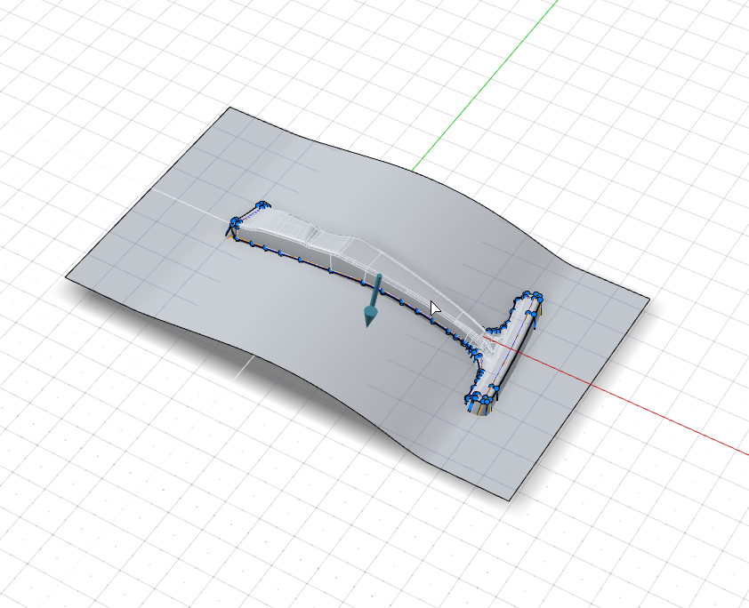
-
Zoom in on the bottom of the handle.
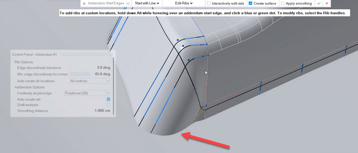
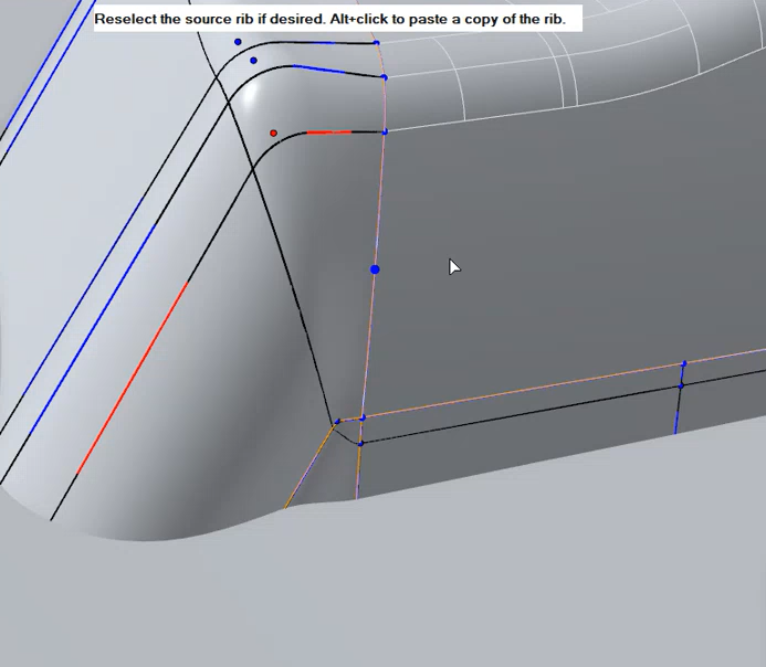
We're going to flatten the bulge (indicated by the red arrow above) by adding a copy of a rib:-
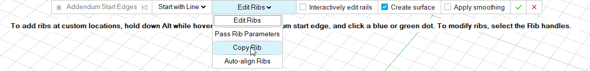
In the guide bar, select Copy Rib.
-
Select the rib to copy (highlighted in orange below).
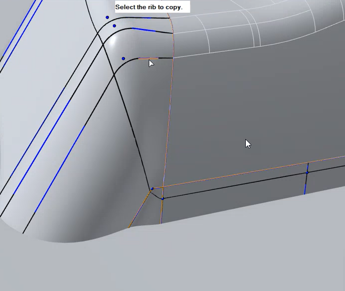
-
Hover along the edge. Blue dots are displayed where you can paste a
copy of the rib. About midway between the neighboring ribs,
Alt+click to place a copy.
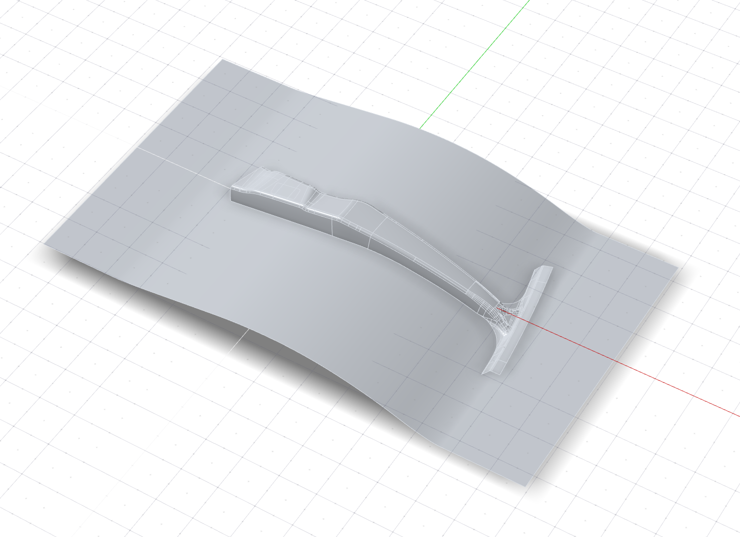
A copy of the rib is added, removing the bulge (indicated by the green arrow).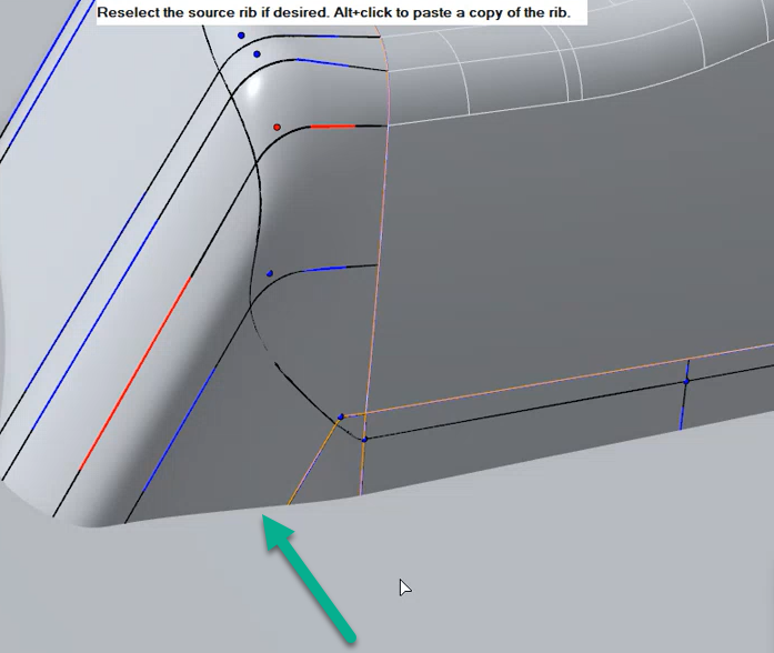
-
In the guide bar, select Copy Rib.
Finalize the Draw Die
Finalize the die by creating a fillet along the edge of the binder.
-
Click the Die icon.

-
Click the Die subtool.
-
Select the binder (outlined in orange).
The binder is selected and the part is outlined in green.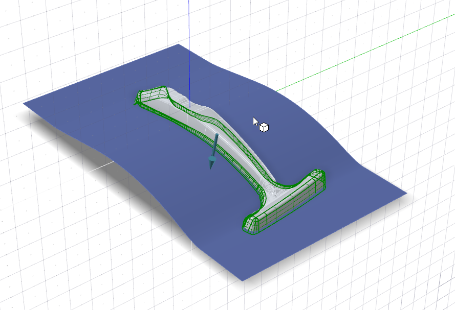
-
For the fillet method, keep the default Edge Fillet
option. To confirm, right-click.

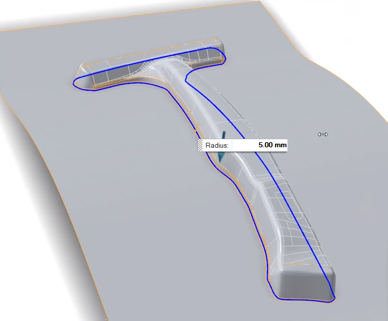
A fillet is created using the Round tool from Inspire Studio. -
To define the same radius for all fillets, enter a
Radius of 5.00 mm.