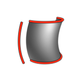
Sweep
Sweep one or more curves along an extrusion path to create a 3D surface.
This tool has an Auto-alignment option.
Create a Sweep
Create a new surface by sweeping one or more profile curves or surface edges along an extrusion path.
- On the ribbon, click the Surfaces tab.
-
Click the Sweep icon.
- Click the profiles in sequence, and then right-click to confirm.
-
Click the path curve.
Attention: When the profile does not intersect the path, select Auto-alignment in the guide bar. Otherwise, no result is produced and a red exclamation mark appears in the Model Browser.
- See Step 2 of Edit a Sweep.
- Right-click and mouse through the check mark to exit, or double-right-click.
Edit a Sweep
Modify the orientation, position, and shape of the sweep.
-
Double-click the sweep.
To Do this Note Reselect the profiles - In the guide bar, click Profiles.
- Click the profiles you want to add or remove.
- Right-click to confirm.
Reselect the path - In the guide bar, click Path.
- Click a path.
- Right-click to confirm.
Add or remove caps - To add caps to both ends, in the guide bar, click Caps.
- To add or remove a cap from either end, click a red oval at either end.
Auto-align the profiles See Auto-align the Profiles. Define other options In the guide bar, click Options, and then select from the following options: - Arc Length Profiles: If the parametrization of the profiles is uneven, evenly space the isoparms of the surface between the profiles for a less stretched shape.
- Arc Length Path: If the parametrization of the path is uneven, evenly space the isoparms along the path for a less stretched shape.
- Extend: Extend the sweep surface the full length of the path, rather than being contained within the profiles. If only one profile is used, the sweep will always extend the full path.
Change the orientation In the guide bar, select one of the following options: - Normal (default): Make the orientation of the surface follow the natural curve of the extrusion path.
- Parallel: Keep the orientation of the surface parallel to the extrusion path.
- Normal to surface:
Lock the direction In the guide bar, select Locked direction. Add a vertex While holding down Alt, hover over a profile to snap to the profile, and then click. An added vertex is indicated by a blue circle.
You can modify the shape of the loft by adding, deleting, and repositioning vertices on the profiles. The more vertices there are, the more control over the sweep.
There are 3 types of vertices:- Original: These are the original vertices present in the profiles used to create the sweep.
- Auto-added or Auto-deleted: Each profile must have the same number of vertices. The applications automatically adds or deletes vertices where needed.
- User-added: These are the vertices that you added. They are displayed as crosses in the modeling views.
Delete a vertex Click the vertex, and then press Alt+D. Delete all added vertices Click a vertex, and then click Reset vertices. Reposition vertices - To select multiple vertices, use box selection.
- Drag to reposition the vertex or vertices.
Create a seam point Click a vertex, and then click Make Seam. A seam point is indicated by a small solid triangle.
You can only create seam points on a closed profile. Reposition a seam point Drag the seam point. Invert the orientation of a profile Click a profile, and then click Invert orientation. The direction of the arrow on the profile or rail indicates its orientation.
In most cases, the optimal orientation of each profile is internally calculated so that the resulting surface is not twisted. In some cases, inverting a profiles orientation will cause the sweep to fail. Scale a profile Click a profile, type the Scale value, and then press Enter. Twist a profile - Click the profile.
- Type the Angle, and then press Enter. The maximum value is 360°.
- Type the number of Turns, and then press Enter. The minimum value is 1.
. Modify the constraint See Modify the Constraint. - Right-click and mouse through the check mark to exit, or double-right-click.
Auto-align the Profiles
Use profiles for the sweep that do not intersect the path.
Profiles are only used as reference. This option comes with extra parameters that allow more control over the position and orientation of each profile.
- Double-click the sweep to enter edit mode.
- In the guide bar, select Auto-alignment.
- Click a profile.
-
Edit the profile:
To Do this Reposition a profile on a point along the path Type a value for Point on path, and then press Enter. Position the profile along the path Choose from the following Reference point options: - Center of b. box: Make the center of the profile boundary the reference point.
- Axes origin: Make the axes origin the reference point.
- Point on profile: Make a point on the profile the reference point. Type value for Point on profile, and then press Enter.
- Invert: Invert the reference point for the sweep.
Rotate the profile around the path's tangent Type the value for Rot. tangent, and then press Enter. Rotate the profile around the path's normal Type the value for Rot. normal, and then press Enter. Rotate the profile around an axis that is perpendicular to the path's tangent and normal Type the value for Rot. vertical, and then press Enter. Reverse the profile order along the path Click Reverse profiles order.