Allows for the study of fatigue performance of spot welds in structures.
Currently, only stress-life (SN) based spot weld fatigue analysis is supported. The
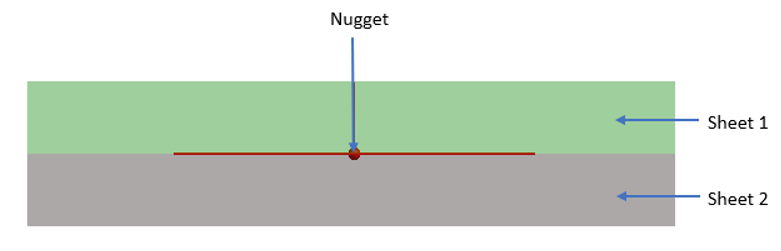
spot weld location is defined by three attributes, sheet 1, sheet 2, and the nugget.
Figure 1. Spot Weld Fatigue
Implementation
Fatigue analysis for spot welds involves examining the weld at three distinct
locations, the sheets and nugget, and is based on a paper by Rupp et al. The
cross-sectional forces and moments at the nugget location are determined and used to
calculate corresponding stresses at the sheets and the nugget. These stresses are
then used to calculate Fatigue Damage using Rainflow counting and the SN
approach.
The following sections illustrate how stresses and subsequently damage are calculated
at each of the three locations.
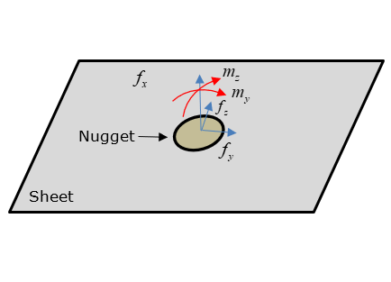
Sheet Location (1 or 2)
Figure 2. Forces and Moments of Interest at Sheet Locations
Radial stresses are calculated at the sheet by considering forces and moments at the
nugget. The radial stresses are calculated as a function of
for each point in the load-time history as:(1)
Where,(2)
(3)
for
for (4)
(5)
Where,
Diameter of the weld element
Thickness of the sheet under consideration for damage calculation
Calculated as
The equivalent radial stresses are calculated at intervals of
(Default =18 degrees). The value of
can be modified by varying the Number of angles field in the spot weld solution
settings. Subsequently, Rainflow cycle counting is used to calculate fatigue life
and damage at each angle (). The worst damage value is then picked for output. A
similar approach is conducted for the other sheet.
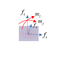
Nugget Location
Figure 3. Forces and Moments of Interest at Nugget Cross-Section
The absolute maximum principal stresses are calculated using the shear stress and
bending stress of the beam element as a function of
for each point in the load-time history as:(6)
(7)
Where,(8)
(9)
for
for (10)
(11)
is the diameter of the weld element.
is the thickness of the sheet under consideration
for damage calculation.
The equivalent maximum absolute principal stresses are calculated for each
from and . These stresses are used for subsequent fatigue
analysis. Rainflow cycle counting is used to calculate fatigue life and damage at
each angle (). The worst damage value is then picked for output.