Emitter
Create a glowing object such as a LED light or a neon sign. You can create a standard emitter, or a physically accurate emitter using an IES file.
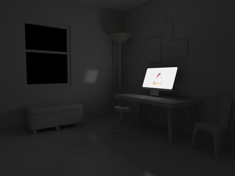 Figure 1. Example of an Emitter with an ISO of 100
-
Click the Materials icon.

Standard Emitter
The following are the parameters for a standard emitter.
Main Parameters
- Color
-
- Select a color.
- Select an image. The image overrides the color.
- To blend the color with the image, click the plus symbol (+). You can tell if the blend option is turned on by looking at the image preview.
- Power Unit
- Define the intensity of the light. The default value is 100 watts.
- Power
- Define the intensity of the light source.
- Efficacy
- Define the luminosity of the light. You can look online for the efficacy of
a specific type of light. For example, see the following Wikipedia page:
Luminous efficacy.Note: This option is only available if the Power Unit is watts or W/sr.
- Caustics
- Select Caustics to achieve a more accurate visualization of
refraction and reflection. For example, you can use this option to render
the shimmering waves of light at the bottom of a swimming pool. Note: This feature is not currently available in GPU+CPU mode.
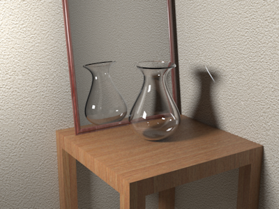 Figure 2. Caustics Off
 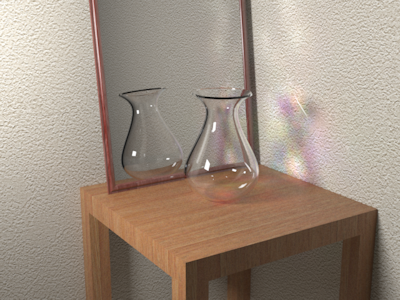 Figure 3. Caustics On
 - Passive Emitter
- A passive emitter doesn't illuminate the scene, but you can still see if it there is no other light source in the scene.
- Invert Light Direction
- If your object is a closed solid, click Invert Light Direction to turn the light on or off.
Advanced Parameters
- Displacement
- Bump allows you to render detailed textures relatively quickly; however,
because you are only changing the surface normals and not the surface
itself, silhouettes and shadows might not be rendered realistically.
This condition is particularly true for larger texture effects. If you
need to give surfaces a greater sense of depth and detail, showing
self-occlusion, self-shadowing, and silhouettes, use Displacement. Like
bump maps, displacement maps are grayscale; black equals zero
displacement and white equals maximum displacement (a value you define
using the Height parameter below).
This feature is not currently available in GPU+CPU mode.
The default number of samples is 500.
Subdivision: Modify the object's number of subdivisions before displacement occurs. Higher values produce more accurate results. Figure 4. Subdivision: 2
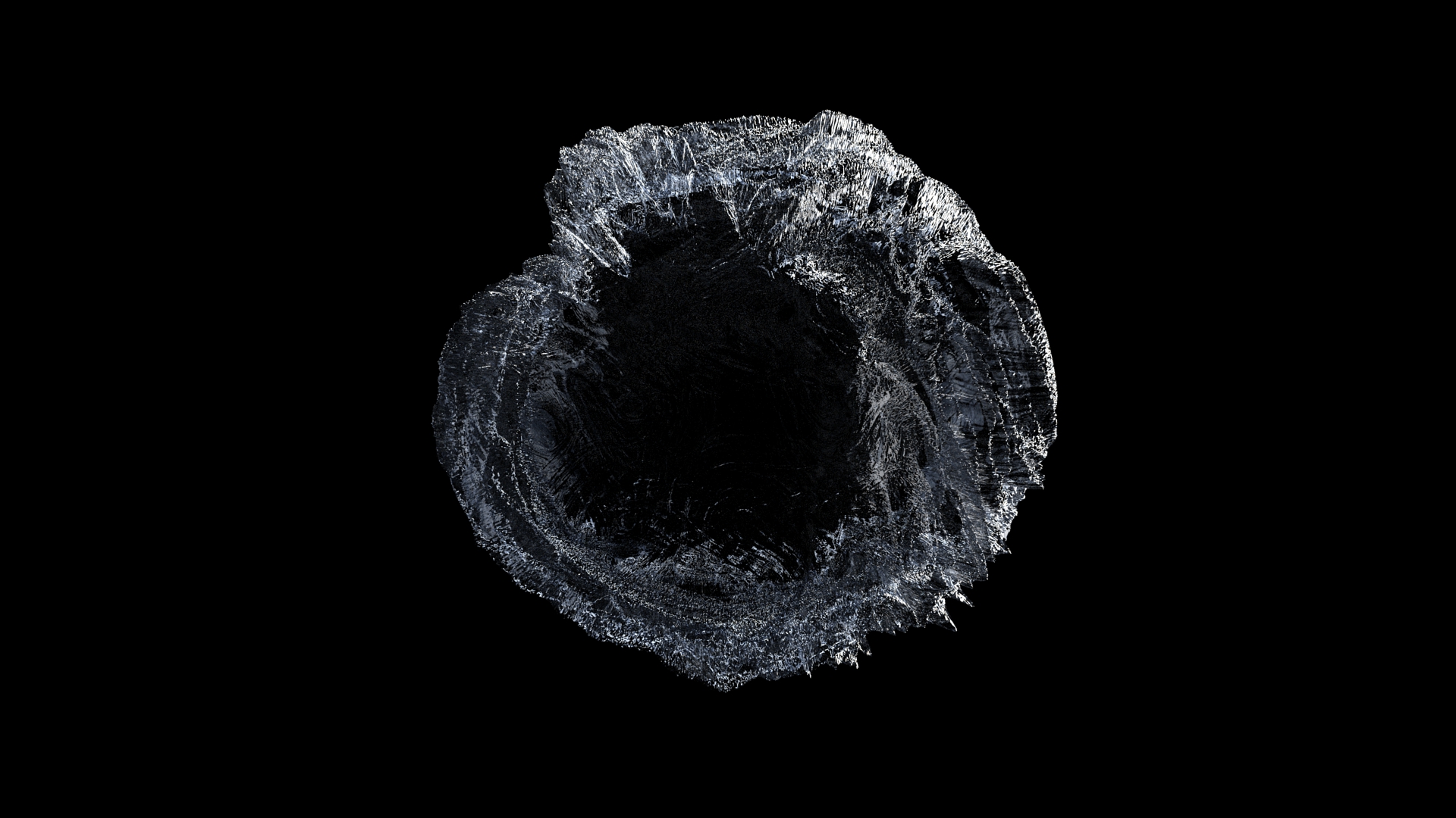 Figure 5. Subdivisions: 6
Texture: Upload a texture map. Colored images will be mapped as grayscale.
Height: Set the maximum distance displaced. For displacement to appear, values must be greater than zero; the default is 2 cm.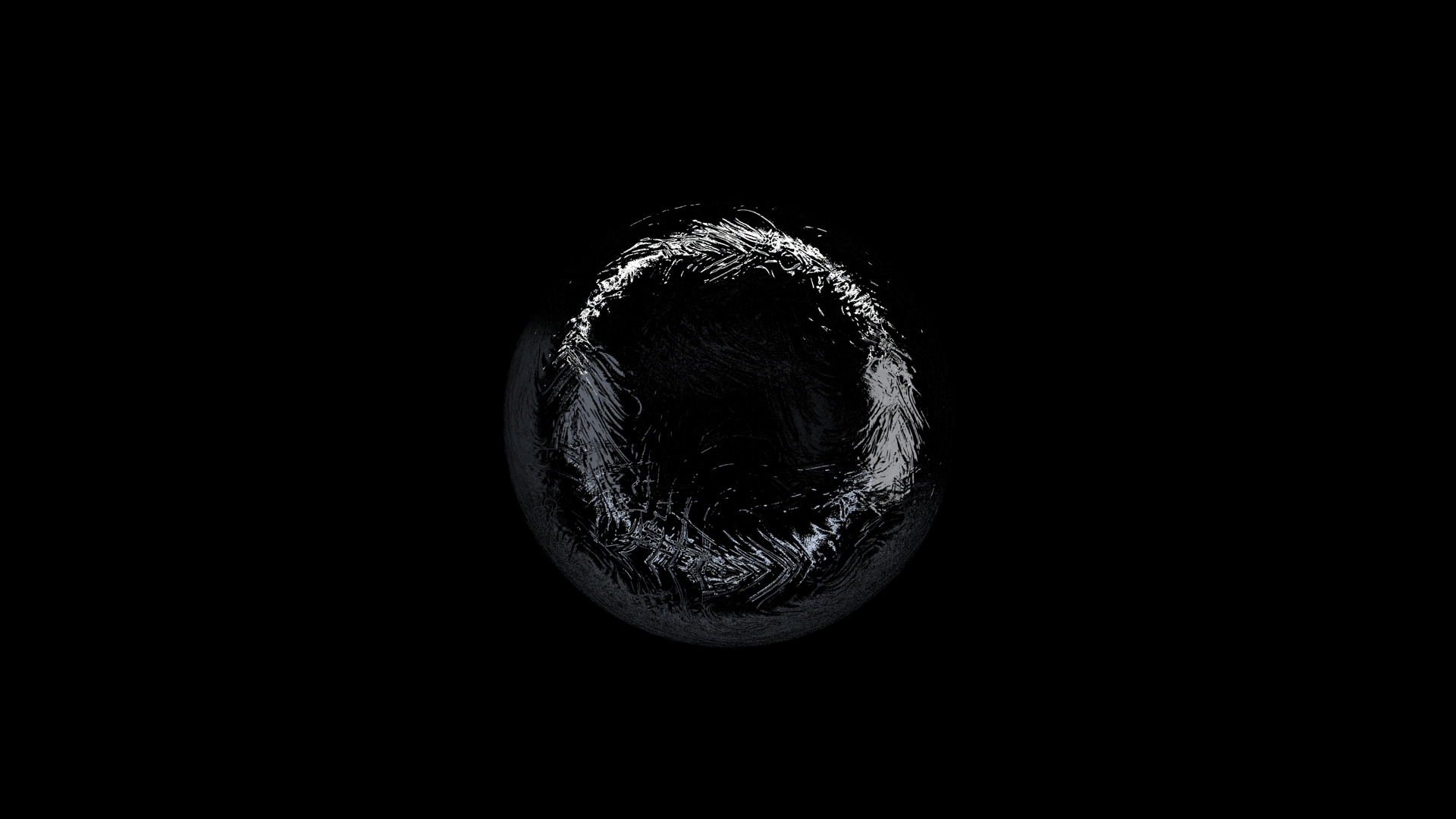 Figure 6. Height: 0.5cm
 Figure 7. Height: 25cmCenter: Invert displacement. This feature is useful for positioning objects along a ground plane. For example, adding a displacement map to a carpet may make it look like it's floating. Reducing your center will bring it back down to the floor. Adding a displacement map to a floor may result in objects intersecting with the floor. In this case, you could increase the center to avoid intersection.
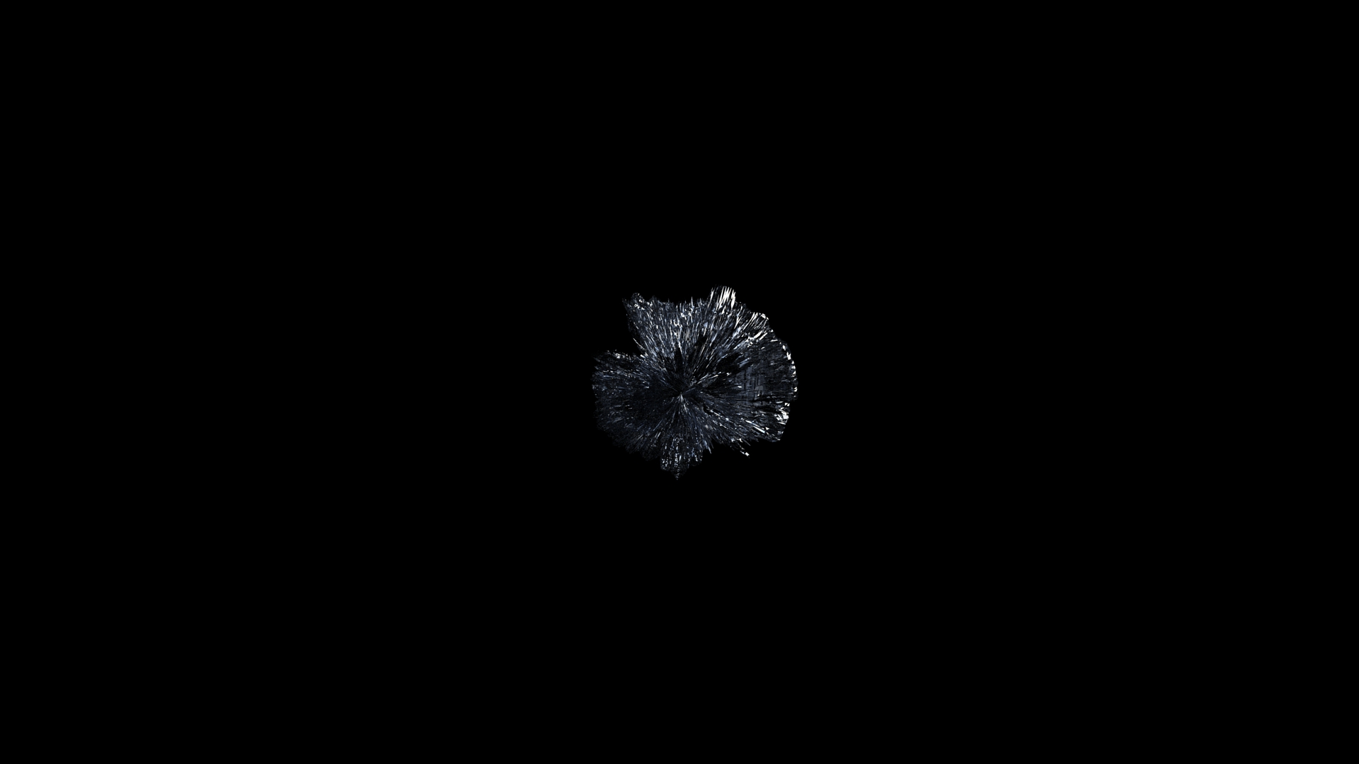 Figure 8. Center: 1cm
 Figure 9. Center: 0.1cmNormal Smoothing: Enabled by default, to render smoothly (continuous shading). Disable to render in a faceted way, which is useful for rendering very sharp, detailed displacements such as sharp corners.
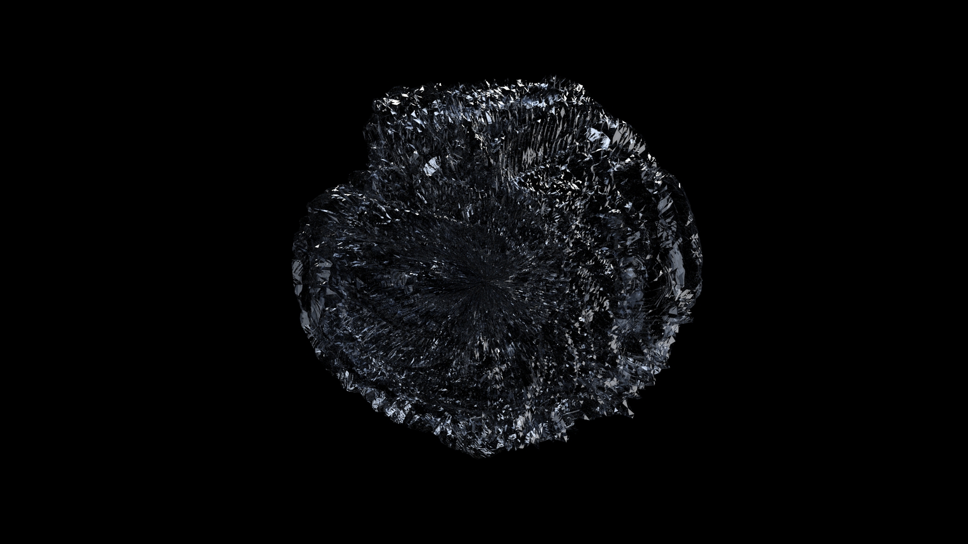 Figure 10. Normal Smoothing Disabled
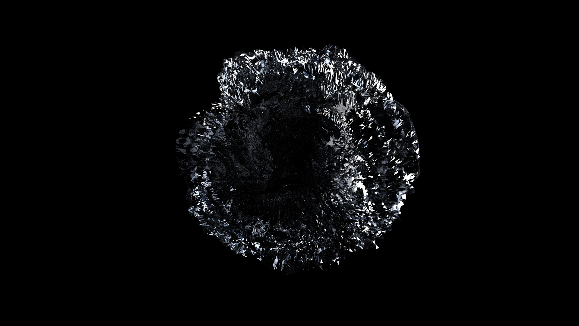 Figure 11. Normal Smoothing OnTight Bounds: Enabled by default. This feature lets Inspire Render compute more precise bounding volumes for the displaced surface, leading to slightly better rendering times. Since this feature is performance-based, check your engine settings to enable your fastest processors.
 Figure 12. Tight Bounds Disabled
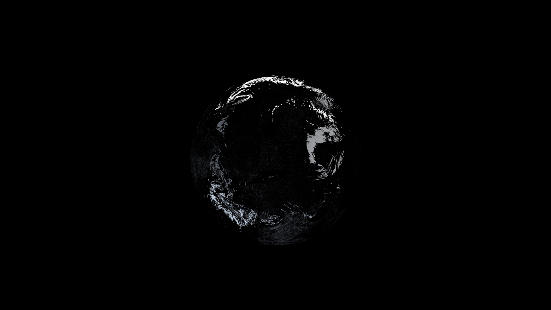 Figure 13. Tight Bounds Enabled
 - Clipping
- Make areas of the material transparent, using a grayscale texture map
where black equals completely transparent and white equals completely
opaque. This feature is useful for quickly creating perforated materials
like a mesh, since you can skip modeling the holes by
hand.
Texture: Upload a texture map. Colored images will be mapped as grayscale.
Threshold (%): Change how the texture map is interpreted. The default is 50, where 50% gray is interpreted as 50% transparent. To make a greater area of the texture transparent; increase the threshold; to make a greater area of the texture opaque, decrease the threshold. At 100, the entire texture is transparent; at 0, the entire texture is opaque.
Soft: Soften the contrast between completely transparent and completely opaque.
IES Emitter
The following are parameters for an IES emitter.
Main Parameters
- Color
- To define the color, choose from the following
options:
- Select a color.
- Select an image. The image overrides the color.
- To blend the color with the image, click the plus symbol (+). You can tell if the blend option is turned on by looking at the image preview.
To define the shade, enter a value of 0-100, where 100 is the true color and 0 is black.
- IES File
- Select an IES file. An IES file is a digital profile of a real world light.
- Multiplier
- Set a multiplier for the inserted IES file. The default value is 1.
- Caustics
- Select Caustics to achieve a more accurate
visualization of refraction and reflection. For example, you can use this
option to render the shimmering waves of light at the bottom of a swimming
pool.Note: This feature is not currently available in GPU+CPU mode.
Figure 14. Caustics Off
Figure 15. Caustics On
- Passive Emitter
- A passive emitter doesn't illuminate the scene, but you can still see if it there is no other light source in the scene.
- Invert Light Direction
- If your object is a closed solid, click Invert Light Direction to turn the light on or off.
Advanced Parameters
- Displacement
- Bump allows you to render detailed textures relatively quickly; however,
because you are only changing the surface normals and not the surface
itself, silhouettes and shadows might not be rendered realistically.
This condition is particularly true for larger texture effects. If you
need to give surfaces a greater sense of depth and detail, showing
self-occlusion, self-shadowing, and silhouettes, use Displacement. Like
bump maps, displacement maps are grayscale; black equals zero
displacement and white equals maximum displacement (a value you define
using the Height parameter below).
This feature is not currently available in GPU+CPU mode.
The default number of samples is 500.
Subdivision: Modify the object's number of subdivisions before displacement occurs. Higher values produce more accurate results.
Figure 16. Subdivision: 2
Figure 17. Subdivisions: 6Texture: Upload a texture map. Colored images will be mapped as grayscale.
Height: Set the maximum distance displaced. For displacement to appear, values must be greater than zero; the default is 2 cm.
Figure 18. Height: 0.5cm
Figure 19. Height: 25cmCenter: Invert displacement. This feature is useful for positioning objects along a ground plane. For example, adding a displacement map to a carpet may make it look like it's floating. Reducing your center will bring it back down to the floor. Adding a displacement map to a floor may result in objects intersecting with the floor. In this case, you could increase the center to avoid intersection.
Figure 20. Center: 1cm
Figure 21. Center: 0.1cmNormal Smoothing: Enabled by default, to render smoothly (continuous shading). Disable to render in a faceted way, which is useful for rendering very sharp, detailed displacements such as sharp corners.
Figure 22. Normal Smoothing Disabled
Figure 23. Normal Smoothing OnTight Bounds: Enabled by default. This feature lets Inspire Render compute more precise bounding volumes for the displaced surface, leading to slightly better rendering times. Since this feature is performance-based, check your engine settings to enable your fastest processors.
Figure 24. Tight Bounds Disabled
Figure 25. Tight Bounds Enabled - Clipping
- Make areas of the material transparent, using a grayscale texture map
where black equals completely transparent and white equals completely
opaque. This feature is useful for quickly creating perforated materials
like a mesh, since you can skip modeling the holes by
hand.
Texture: Upload a texture map. Colored images will be mapped as grayscale.
Threshold (%): Change how the texture map is interpreted. The default is 50, where 50% gray is interpreted as 50% transparent. To make a greater area of the texture transparent; increase the threshold; to make a greater area of the texture opaque, decrease the threshold. At 100, the entire texture is transparent; at 0, the entire texture is opaque.
Soft: Soften the contrast between completely transparent and completely opaque.