Dimension
Use the Dimension tool to define and/or constrain the dimensions of a sketch.
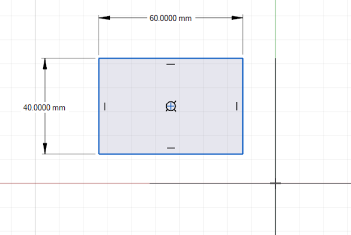
- Vertical, horizontal, or aligned distance between a point, vertex, or entity and the sketch origin. (The sketch origin is a projection of the global origin onto the sketch plane.)
- Vertical, horizontal, or aligned distance between one point or vertex and another
- Distance between two parallel lines
- Diameter of a circle
- Radius of a fillet or arc
- Angles
Driving Dimensions: These dimensions drive the design intent. They can be edited directly through a microdialog either by entering numbers or assigning variables. Changes to driving dimensions will drive changes to reference dimensions.
Reference Dimensions: These dimensions appear in parentheses and cannot be edited directly.
- Decide which dimensions you will want to edit and capture them first. This is easier than changing them from reference dimensions to driving dimensions later.
- Once a rectangle sketch has been defined by two dimensions (e.g. length and width) additional dimensions will be captured as reference dimensions by default.
Apply Dimensions to Sketch Entities
Capture the length of a line, the diameter of a circle, the radius of an arc, or the distance between two sketch entities.
-
In an active sketch, open the Dimension tool:
- On the Sketch ribbon, select the
Dimension icon
 OR
OR - On your keyboard, press the D key
- On the Sketch ribbon, select the
Dimension icon
- Optional:
To apply a variable, click the
 icon on the microdialog and
select a variable from the dropdown menu, or select Add
Variable to create a new variable based on the driving
dimension.
icon on the microdialog and
select a variable from the dropdown menu, or select Add
Variable to create a new variable based on the driving
dimension.
Apply a Variable to a Parameter
Apply a variable to a parameter, or create a new variable on the fly from a tool microdialog.
You can apply existing variables and add new ones via the microdialog in various sketch and geometry tools.
-
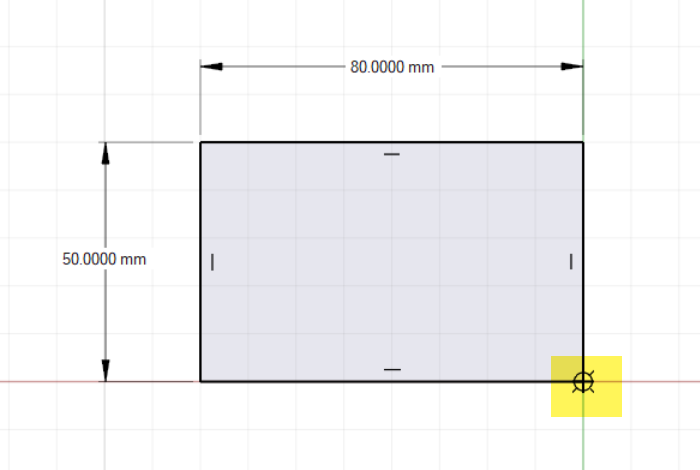
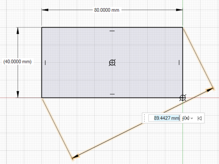
In the tool’s microdialog, click the f(x) icon.
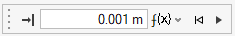
Figure 1. Example of a microdialog with a variable field
- You can also create a variable by entering a new name and expression in the
microdialog’s text field, for example:
Variable1=50 - In addition, you can also create a new variable based on an existing
variable, for example,
Variable2=Variable1*0.5.
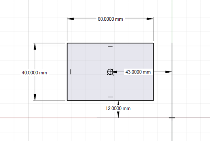
Fully Define a Sketch
A sketch is fullly defined when its dimensions and its position relative to the point of origin have been defined. A fully defined sketch will appear in black.
-
In an active sketch, open the Dimension tool:
- On the Sketch ribbon, select the
Dimension icon
OR - On your keyboard, press the D key.
- On the Sketch ribbon, select the
Dimension icon
-
Apply dimensions to the sketch.
-
Apply dimensions between the sketch and the point of origin.
-
Right-click and mouse through the check mark to exit, or double-right-click.
Tip:
The easiest way to fully define a sketch is to start it from the global point of origin.
Edit a Driving Dimension
Reposition, change the value of, or delete a dimensional constraint.
-
In the microdialog:
- Enter the desired dimension in the text field OR
- Select the icon the assign a
variable to the dimension
Edit a Reference Dimension
Convert a reference dimension to a driving dimension and edit it.
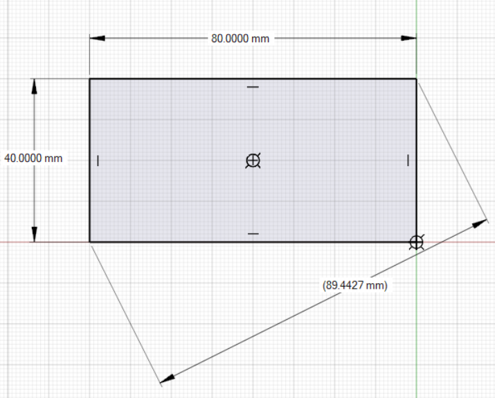
-
Deselect Reference on the context menu.
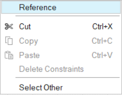
The dimension will appear as a driving dimension (without parentheses), but the sketch may now be colored magenta, indicating that it is overconstrained.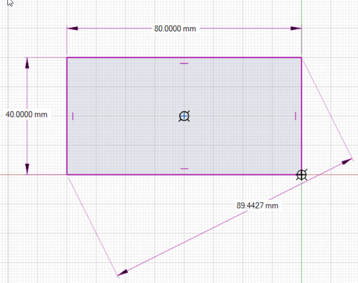
-
Right-click one of the other dimensions. Select
Reference in the context menu.
The dimension now appears in parentheses, indicating that it is a reference dimension. The sketch is no longer colored magenta.
-
Select the dimension you wish to edit.
-
In the microdialog:
- Enter the desired dimension in the text field, OR
- Select the icon to assign a
variable to the dimension.