Traction Control System
Critical driving situations can occur not only while braking, but also whenever strong longitudinal forces are transferred at the contact area between the tire and the ground. This is because the transferable lateral forces are reduced as excessive longitudinal slip is introduced. Critical situations can also occur when starting off and accelerating, particularly on a slippery road surface, on hills, and when cornering. These kinds of situations can make the driver react incorrectly and the vehicle to become unstable.
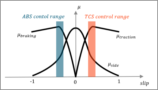
Figure 1.
In modern vehicles the throttle pedal is connected to a sensor, at which the throttle position is measured. The vehicle’s computer sends the measured signal to the throttle actuator controlling the engine intake. This set up is called drive by wire and it is necessary for TC function. TC utilizes wheel speeds sensors and an accelerometer to calculate longitudinal slip and then regulates driver’s throttle reference to prevent wheels from spinning.
When you build a car/light truck model using the Assembly Wizard, you can select to include a Traction Control System. The TC in MotionView system collects information like wheel speeds, vehicle longitudinal acceleration, and Driver throttle demand from the MotionView model as input to the TC Activate Model imported into MotionView as a Functional Mock-up Unit (FMU). The TC Activate Model estimates the wheel slips and outputs the modulate throttle to the MotionView powertrain system. The powertrain system then outputs the equivalent torque to drive the vehicle based on the modulated throttle. The Traction Controller Activate model (.scm file) is included in the MDL Library for viewing and editing (…\hwdesktop\hw\mdl\mdllib\Common\FMU_Library\TC).
The figure below shows the schematic relationship between the TC Activate Model and the MotionView powertrain model.
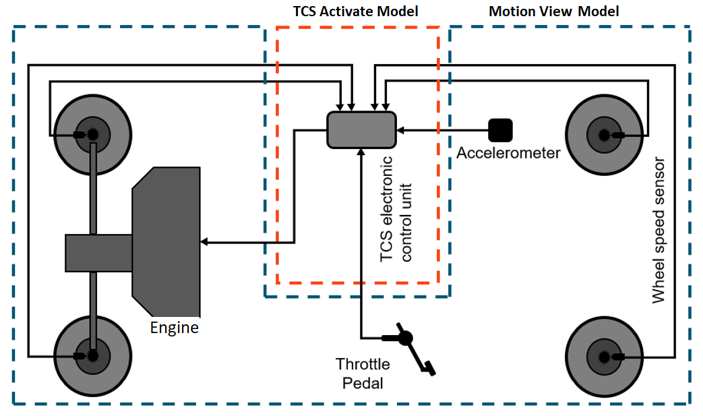
Figure 2.
TC Modules in Activate
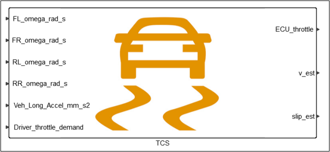
Figure 3.
TC Throttle Controller
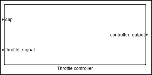
Figure 4.
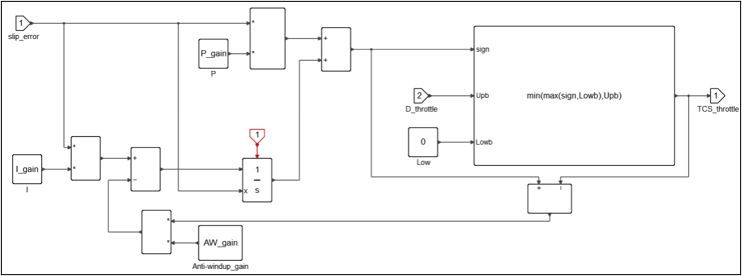
Figure 5.
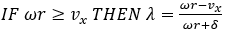
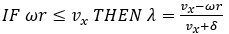
 : longitudinal slip
 : wheels rotational velocity
 : vehicle’s longitudinal velocity
 : tires radius
 : a small number
  to avoid undefined value when = 0
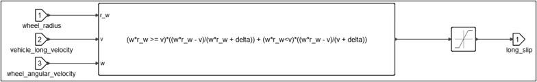
Figure 6.
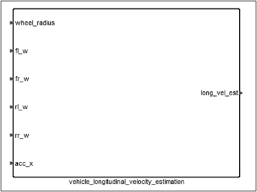
Figure 7.
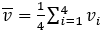
- Average wheel speed of the four tires
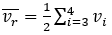
- Average wheel speed of the two non-driven tires
- Longitudinal Acceleration

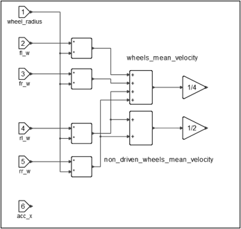
Figure 8.
 Vehicle's velocity is very low
 Vehicle is accelerating
 Vehicle has constant velocity or decelerating softly
 Vehicle is decelerating
Status is computed based on the previous step status and some threshold values alongside with some hysteresis in order to keep the algorithm stable.
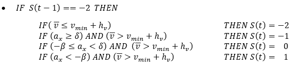
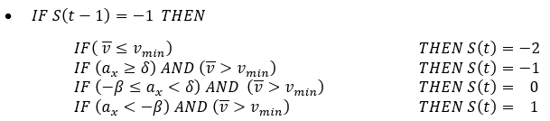

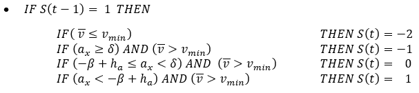
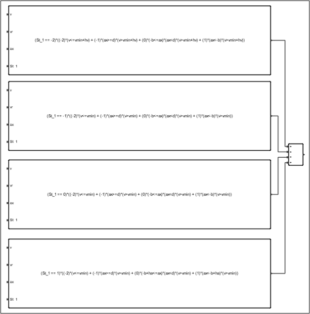
Figure 9.

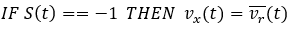


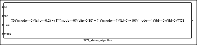
Figure 10.
Figure 11.
Create a Vehicle Model with Traction Control System (TC)
- Load the MBD-Vehicle Dynamics Tools preference file ()
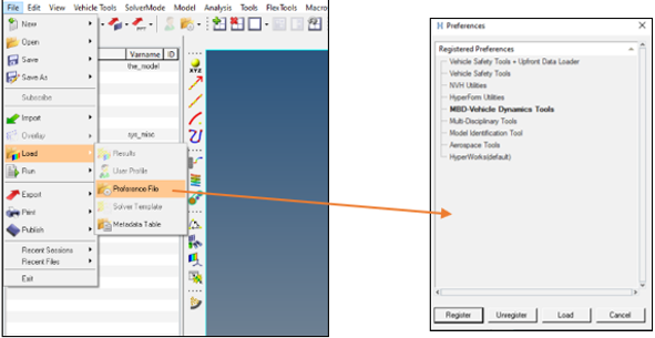
Figure 12. - From the Model tab, select the Set Wizard Path and pick Car/Small Truck.
- From the Model tab, select the Assembly Wizard.
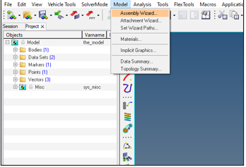
Figure 13. - On Page 8 of the dialog, select Traction Controller (TC).
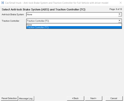
Figure 14.
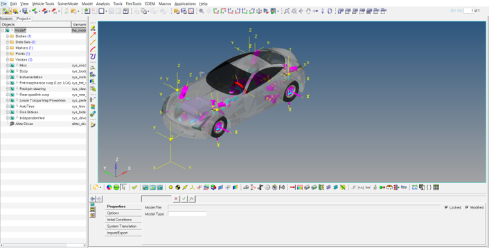
Figure 15.
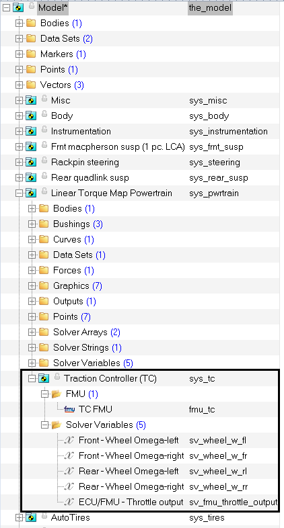
Figure 16.