FMU based Electric Powertrain with Regenerative Braking
- IC Engine with Transmission
- Battery Electric Vehicle
- Hybrid Electric Vehicle
There are variations in the type of components used and the architecture of powertrains, however the responsibility of the powertrain remains the same. It must deliver torque to vehicle by converting fuel/electric energy to kinetic energy.
The FMU powertrain interface provides you with the ability to simulate such variations in powertrain models with MotionView/MotionSolve using the FMU/FMI interface.
Access the Electric Powertrain for Full Vehicle Models
- From the File menu, select .
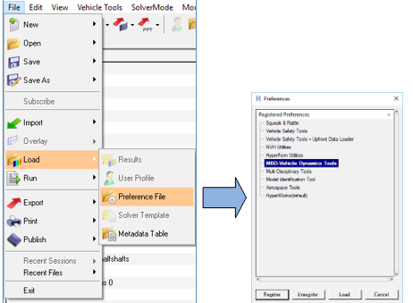
Figure 1. - From the Model menu, select Assembly Wizard.
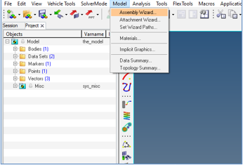
Figure 2. - Select Electric Powertrain (FMU) from the Powertrain option
drop-down menu.
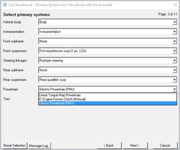
Figure 3. - Upon finishing the vehicle building process, a full vehicle with Electric Powertrain
(FMU) is loaded in MotionView.
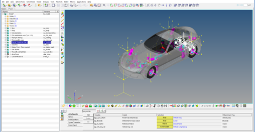
Figure 4.
Interface
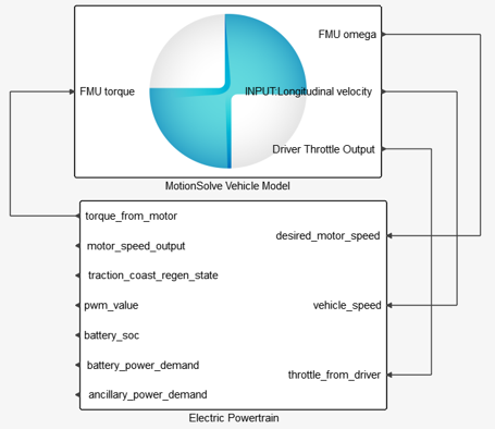
Figure 5.
Schematic
A schematic is shown below: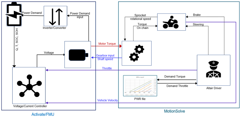
Figure 6.
Theory and Equations
- Permanent Magnet Synchronous Motor (PMSM Motor)
- A simplistic model of PMSM motor is defined using the speed torque characteristics
of motor. The model consists of two boundaries as shown in image below. The boundaries
show the maximum positive and negative torque that motor can deliver. The PMSM motor
characteristics consist of a constant torque and constant power region. The motor can
deliver maximum torque till rated speed and after that it can deliver maximum
power.
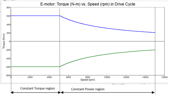
Figure 7. - Voltage/Current Controller
- This controls the voltage that is applied to the motor. The control voltage depends
on the vehicle speed, motor speed, accelerator pedal input and battery state of
charge. The controller uses Pulse Width Modulation or PWM and Torque lookup tables to
find the correct voltage to be applied to the motor. The voltage is also constrained
by the battery State Of Charge (SOC). If the battery SOC is greater than 80% then the
controller does not allow the regenerative braking as it can cause the damage to
battery cells. If the battery SOC goes below 20 % then the battery does not supply the
current, this is again to save the cells from damage.
PWM Look Up table is used to calculate the PWM value using vehicle speed and accelerator pedal input. The PWM value ranges from 0 to 250. The value 50 is used for coasting, in other words at this value the motor will output 0 torque. If the PWM value is less than 50 then it means that the motor is acting as a generator and is in regenerative mode. A PWM value greater than 50 means the motor is providing positive torque for traction. The coasting region consist of two boundaries as shown in image below.
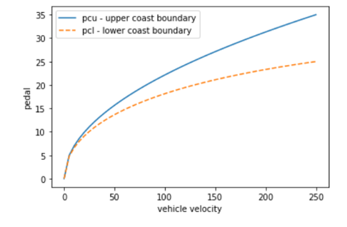
Figure 8.The region above pcu is the tractive region and the region below the lower boundary (pcl) is the regenerative region. The coasting band between these boundaries increases with vehicle speed. This is done to make the accelerator pedal less sensitive at higher vehicle speed. These PWM values can be mapped to voltage values or demand torque values. The 3D PWM characteristics are shown in image below.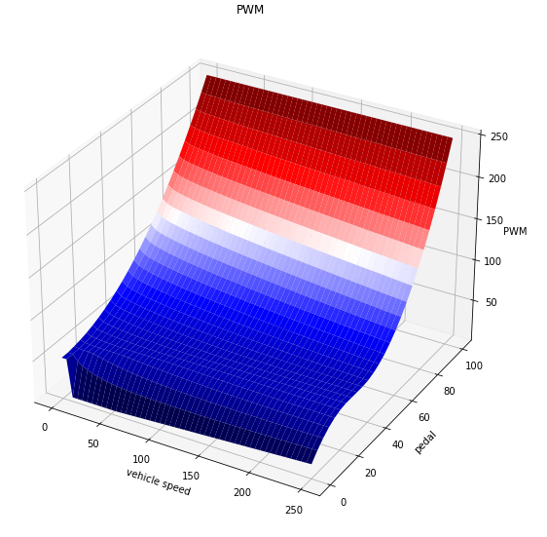
Figure 9.The Torque lookup table takes the PWM value, motor speed as input and generates the torque demand for motor. The regenerative torque in the Powertrain can be used to brake the vehicle in normal traffic condition. The motor provides enough negative torque to operate the vehicle with only one pedal in case of city drives. At higher vehicle velocities, the regenerative torque alone is not sufficient to stop the vehicle and hence the friction braking should be used. The regenerative torque values in this model changes with vehicle velocity as shown in image below.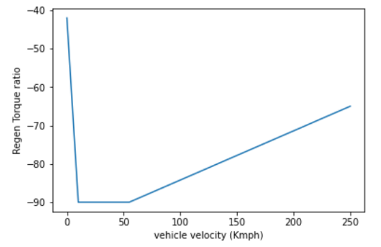
Figure 10.To achieve standstill condition in case of a fully released accelerator pedal, the regenerative torque is set to 0 at 0 vehicle speed. This is done by setting value of the first cell in PWM lookup table to 50 which means coasting.
The image below shows the 3D Torque characteristics of the powertrain based on motor speed and PWM values.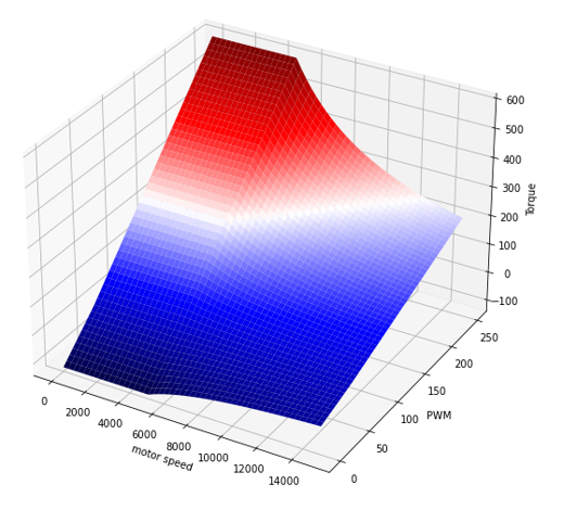
Figure 11. - Inverter/Converter
- The Inverter/Converter are not modeled completely, instead their power losses are considered.
- Battery
- The Battery model consists of parameters like cell voltage, number of cells, modules in series and parallel to calculate the battery capacity. The model is used to estimate the state of charge of the battery.
Activate Model of Electric Powertrain
The Activate diagram of the powertrain model can be accessed from: <install_dir>\hwdesktop\hw\mdl\mdllib\Common\FMU_Library\Motor\FMU_source\Activate_Models.
Powertrain MDL System
- Motor (FMU)
- It represents the lumped mass and inertia of the motor in a non-operating condition. The motor’s output shaft is assumed to be hard coupled with gearbox input shaft and hence their speed is going to be the same. The motor’s shaft and its rotation are not modeled. Since the inertia of the rotating shaft is not modeled, this inertia can be added in other rotating elements in the driveline.
- Motor/Engine Mounts
- Motor is attached to the chassis by bushings. You must provide the mount locations on the attachment body by specifying the coordinates of the mounts. The orientation of the bushings must be specified using the vectors corresponding to each mount.
- Inputs
-
Entities Type Description Comments Driver Throttle Output Attachment Solver Variable Throttle signal from Driver. 0-1 Motor Mount Body Attachment Body The Vehicle's Body/Frame. Reference Marker Attachment Marker Reference marker for powertrain orientation. Transmission Speed Attachment Solver Variable Gearbox input shaft speed. FMU Torque Solver Variable The torque from engine/motor to transmission. N-m FMU Omega Solver Variable The rotational speed of engine/motor, it will equal to the gearbox input shaft speed. rad/sec Get Torque Given Throttle Solver Variable User subroutine which creates a reduced dof model of Powertrain to help Altair Driver in predicting the demand throttle values. FMU FMU Contains the powertrain model wrapped in an FMU. The FMU contains the battery, inverter, motor, and motor controller model inside it. Transmission/Gear Box System Contains the entities required to model a constant reduction or a manual gearbox. Engine/Motor Characteristics System This system uses the engine/motor to estimate the model states in case of feed-forward driver events. - Get Torque Given Throttle
- This solver variable is necessary in case the model contains the Altair Driver. It creates a reduced degree of freedom model of
Powertrain inside MotionSolve using the
.pwr file. It is used by the Altair
Driver in case of feed forward events to look for demand throttle based on demand
torque values. The function call needs the powertrain properties dataset along with
the throttle value and the gearbox input shaft rotational speed which is assumed to be
hard coupled with the motor output shaft. The signature of the function call is as
follows:
Varsub DLL Name Function Name Signature Get Torque Given Throttle msautoutils POWERTRAIN_VARSUB `USER(6, {sa_powertrain_properties.idstring}, {arg_sv_driver_throttle_output.idstring}, {arg_gb_input_shaft_speed.idstring})`Powertrain Properties DatasetInputs Description Comments Max Voltage Not used Motor Engine Efficiency Not used Rotor Inertia Value can be added in other rotating parts of the vehicle. Not used FMU Motor/Engine Property Contains the speed torque characteristics of powertrain. The file extension is “.pwr”. The .pwr file is based on the TeimOrbit format. It contains the torque values based on throttle and motor speed. A sample file is shown below: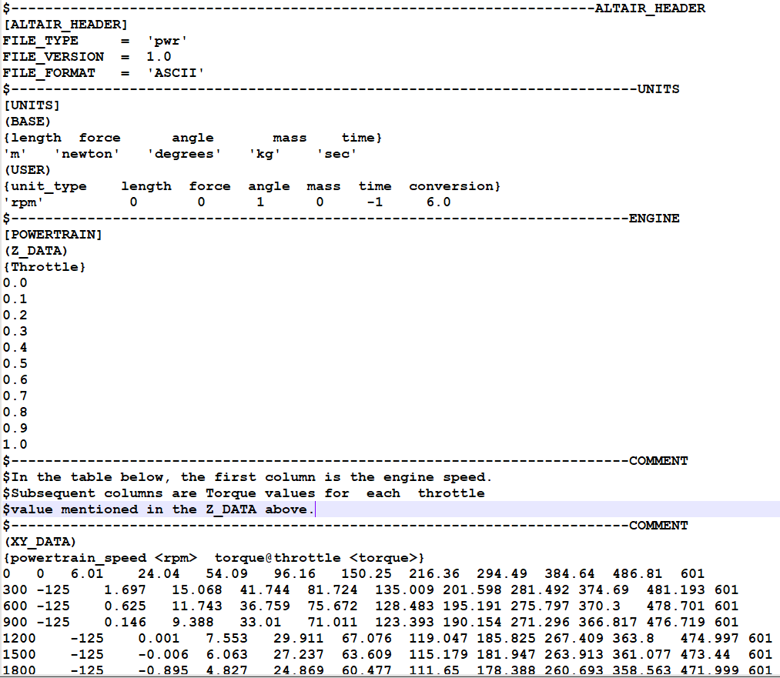
- FMU Inputs and Outputs
- The inputs of the FMU powertrain can be customized and you are free to change the
system, however some inputs and output need to be present to correctly simulate a
driver event. The schematic shows the necessary inputs and outputs of FMU powertrain
block. The powertrain takes throttle, transmission input shaft speed, vehicle speed,
and outputs torque.
Figure 12.Connections Type Description Units Desired Motor Speed Input to FMU Gearbox input shaft speed. rad per sec Vehicle Speed Input to FMU Vehicle's longitudinal velocity. mm/s Throttle from Driver Input to FMU The accelerator pedal's input from Driver. 0-1 Torque from Motor Output from FMU The output torque from motor. N-mm Motor Speed Output Output from FMU Motor shaft speed. Rad per sec Traction Coast Regen State Output from FMU Integer value that shows the operating mode of powertrain.
-1 indicates that powertrain is in regenerative braking mode, 0 means it is operating in coasting band, and a value of 1 indicates that the motor is operating in tractive region.-1, 0, 1 PWM Value Output from FMU It corresponds to the pulse width modulation value which can be converted to voltage applied to the motor. 0-250 Battery SOC Output from FMU The state of charge of the battery. 0 -1 Battery Power Demand Output from FMU The power demand to the battery, it also included the Ancillary power demand. Watt Ancillary Power Demand Output from FMU Power demand due to ancillary services. Watt
Engine/Motor Characteristics
This system acts as a bridge between the FMU based powertrain and Altair Driver. The Altair Driver calculates the demand torque values in case of feed forward events and it needs the demand throttle values to follow. The demand throttle values either can be supplied to the Driver or the Driver is asked to calculate the demand throttle values by doing an inverse look up in PWR file which contains the torque speed characteristics of Powertrain.
- Internal
- This predictor relies on Altair Driver to calculates the
demand torque value. The Altair Driver calculates the
torque demand based on the Driver event information. This torque demand value is
filled inside the ‘Get Demand Torque’ solver variable using a varsub call. Based on
the torque demand, the Altair Driver also calculates the
throttle demand using the torque speed characteristics of powertrain. The throttle
demand value is filled inside the ‘Get Demand Throttle’ solver variable using a Varsub
call.The signatures of the Varsub used in an internal predictor are as follows:
Varsub DLL Name Function Name Signature Get Demand Torque msautoutils POWERTRAIN_VARSUB 'USER(7)' Get Demand Throttle msautoutils POWERTRAIN_VARSUB 'USER(4)' - External
- This predictor relies on external information to calculate the throttle demand for
Powertrain. In this case, the demand torque is calculated by Altair Drivers based in the driver event information. The torque
demand is filled inside the ‘Get Demand Torque’ solver variable using a Varsub call.
You can choose to use this torque demand value or they can use their mathematical
model to calculate demand throttle value. Once the throttle demand is calculated, it
needs to be passed on to the ‘Set Demand Throttle’ solver variable using a Varsub
call. The system contains an extra variable named ‘Throttle Demand’ which can be used
to fill the calculated demand throttle value; this solver variable is an input to ‘Set
Demand Throttle’.The signature used for the Varsub in an external predictor are as follows:
Varsub DLL Name Function Name Signature Get Demand Torque msautoutils POWERTRAIN_VARSUB 'USER(7)' Get Demand Throttle msautoutils POWERTRAIN_VARSUB 'USER(5, {sv_throttle_demand.idstring} )' Throttle Demand - - Should contain a real value and needs user defined inputs.
Limitations
- The unit’s information is not picked up from the .pwr file. Currently the torque must be in Nm, the engine speed in RPM, and the throttle between 0 and 1.
- The rotational inertia of the motor’s shaft should be added in the rotating bodies in the driveline.
References
Design and realization of a One-Pedal-Driving algorithm for the TU/e Lupo EL
J.J.P. van Boekel1, I.J.M Besselink1, H. Nijmeijer1