HS - 1650: Beam Cross-Section Study with Inspire Studio
In this tutorial, you will perform geometric changes in Inspire Studio via HyperStudy and study the effect
of each dimension on responses.
Before you begin, copy the model files used in this tutorial
from <hst.zip>/HS-1650/ to your working directory.
In this tutorial, you will:
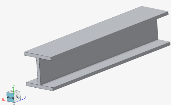
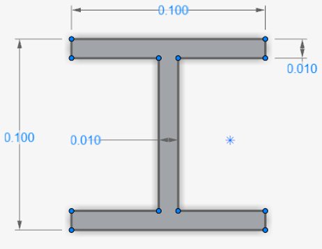
Use Inspire Studio to change dimensions of an
I-beam cross-section and generate a new CAD file.
Read the CAD file into HyperMesh and prepare a
finite element model via automation script.
Run the finite element model in OptiStruct and
extract displacement results.
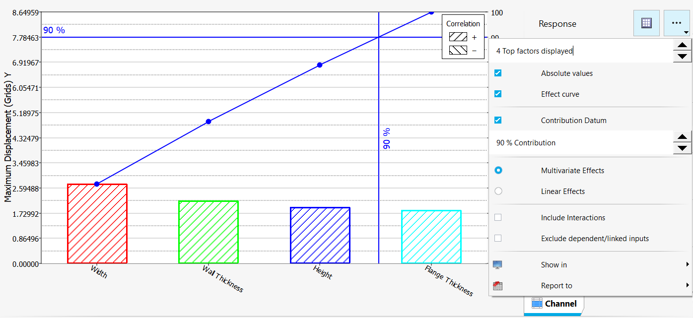
Design Variables:
Width
Height
Web Thickness
Flange Thickness
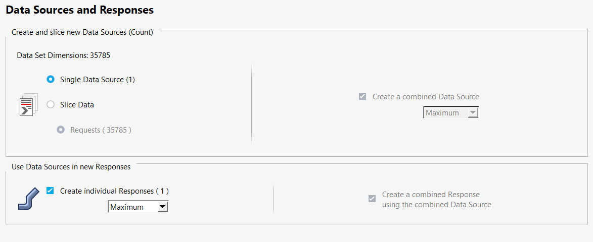
Response: Maximum Deflection along the Y-axis
Finite Element Model:
Hexahedral Mesh
Fixed in all directions at one end
Bending load applied in positive Y direction at the other end
Figure 1. Figure 2.
Specify Design Variables in Inspire Studio
Open Inspire Studio.
Open model.
From the menu bar, click File > Open.
In the Open File dialog, open
Ibeam.iStudio from the working directory.
From the Analysis ribbon, Design
Table group, click the Design Table
tool.
The Design Table dialog opens.
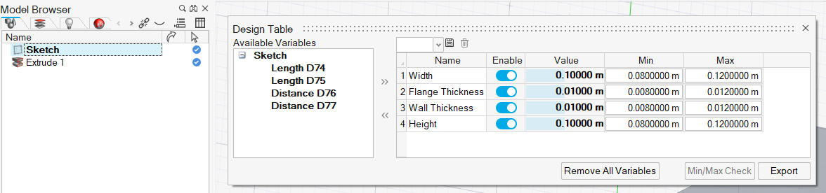
In the Model Browser, select
Sketch to populate the Design
Table dialog with available variables.
Figure 3.
Select all the variables, move them to the right window, and specify the Min
and Max values as shown below.
Unit of all dimensions are in meters.
Variables
Name
Min
Max
Length D74
Width
0.08
0.12
Length D75
Flange Thickness
0.008
0.012
Distance D76
Wall Thickness
0.008
0.012
Distance D77
Height
0.08
0.12
Click Export and save the file as
Ibeam.ist2hst to the working directory.
The Ibeam.ist2hst contains all the necessary attributes
of each variable to be read by HyperStudy.
Setup Inspire Studio Model
Start HyperStudy.
Start a new study in the following ways:
From the menu bar, click File > New.
On the ribbon, click .
In the Add Study dialog, enter a study name, select a
location for the study, and click OK.
Go to the Define Models step.
Add the Inspire Studio model by
dragging-and-dropping the Ibeam.ist2hst file from the
Directory into the work area.
The Resource, Solver input file fields are populated.
Change the extension Solver Input File to .x_t.
Inspire Studio connection provides the CAD file in
Parasolid format, so the extension of the
Solver Input file is Ibeam.x_t. Figure 4.
Click Import Variables.
Ten input variables are imported from the
Ibeam.ist2hst file.
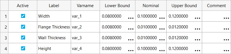
Go to the Define Input Variables step and review the
input variables.
Figure 5.
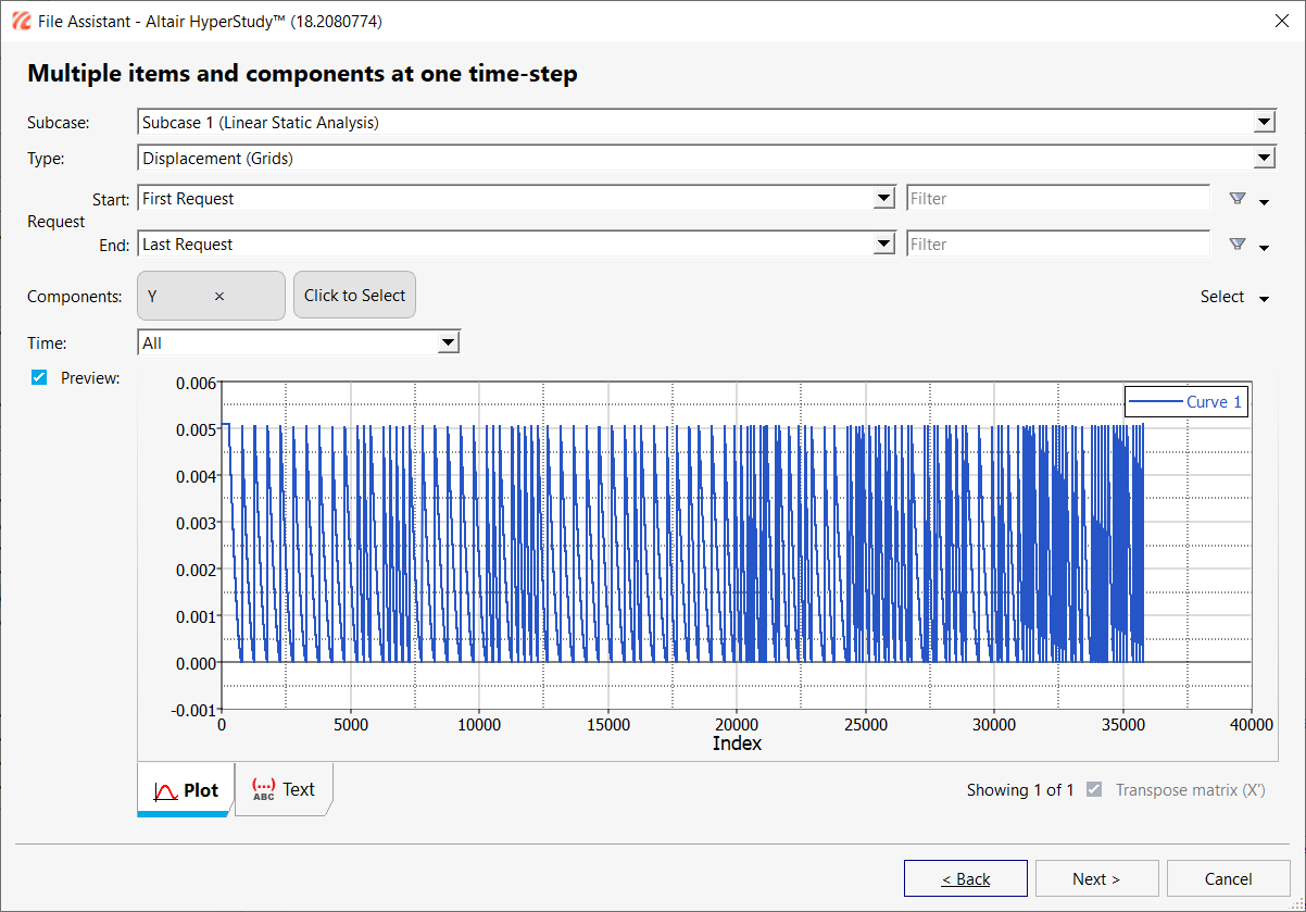
Go to the Test Models step and click Run
Definition.
An approaches/setup_1-def/ directory is created
inside the study Directory. The
approaches/setup_1-def/run__00001/m_1 directory
contains the output file (Ibeam.iges), which is the result
of the nominal run.
Setup HyperMesh Batch Operator Model
After the Inspire Studio Model run is complete, a
geometry file, Ibeam.iges, is output. This file is read by
HyperMesh and a finite element model
(Ibeam.fem) is prepared via the
automation.tcl script in the working directory.
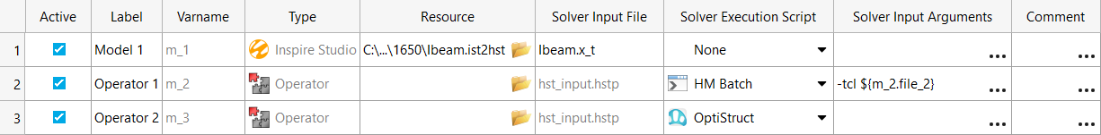
Go to the Define Models step.
Add an Operator model.
Click Add Model.
In the Add - Altair HyperStudy dialog, select
Operator and click OK.
Set the Solver Execution Script to HM
Batch.
Figure 6.
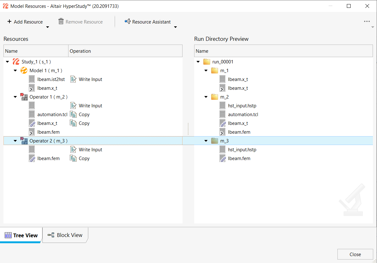
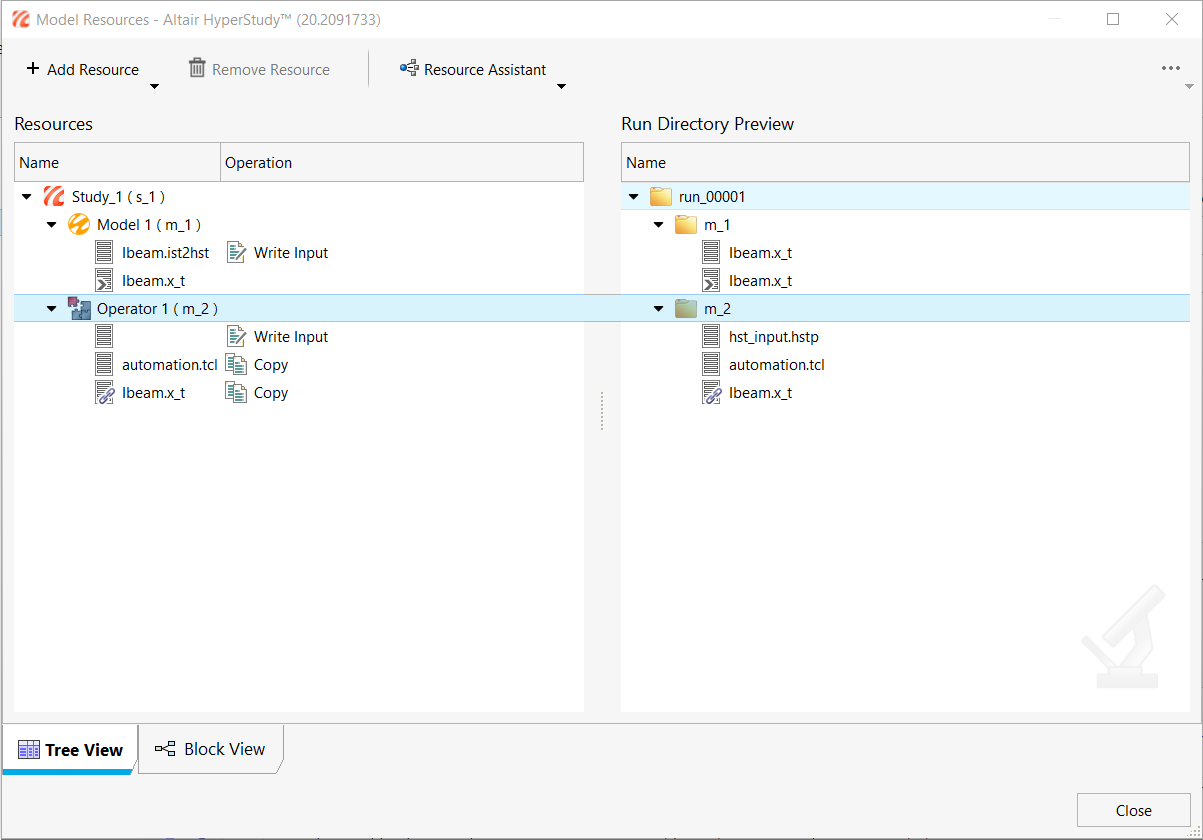
Click Model Resources.
The Model Resources dialog opens.
In the Model Resources dialog, define a model dependency
that references a tcl script to be used as the automation script.
Select Operator 1 (m_2).
Click Resource Assistant > Add File.
In the Select File dialog, navigate to the working
directory and add automation.tcl.
Set the automation.tcl Operation to
Copy.
Repeat step 4 to
define another model dependency using the Ibeam.x_t file
found here: approaches/setup_1-def/run__00001/m_1.
Review the Model Resources window and click Close.
Figure 7.
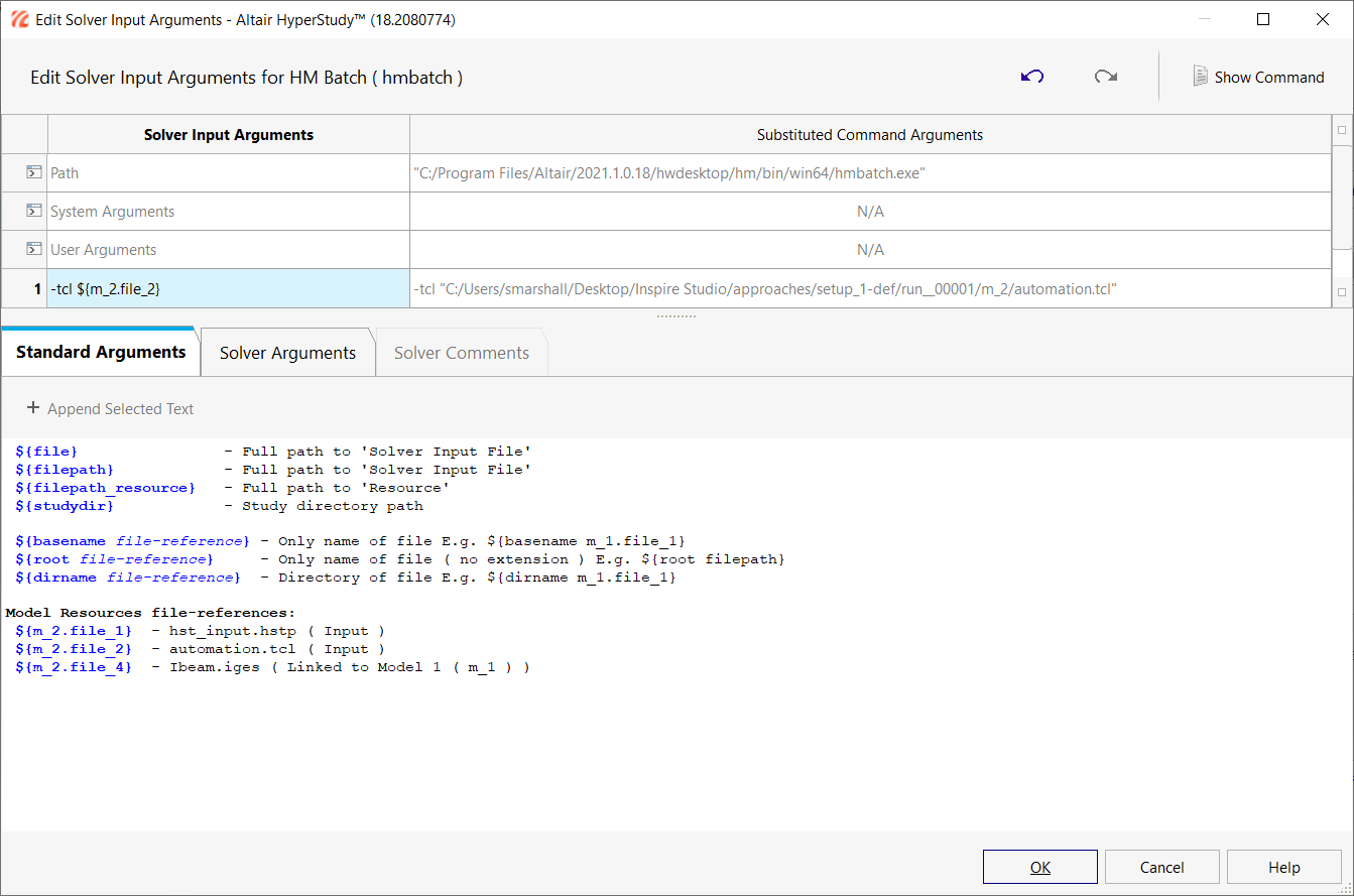
In the Solver Input Arguments field for Operator 1, click and enter the arguments as shown below and click
OK.
Figure 8.
The argument (m_2.file_2) is a reference to the model
resource varname and tells HyperMesh Batch which
tcl script to run.
 .
.

 and enter the arguments as shown below and click
OK.
and enter the arguments as shown below and click
OK.