HM-4910: Set up a MADYMO Occupant Safety Analysis in HyperMesh
In this tutorial, you will load the MADYMO user profile and import XML files.
- truck_model.xml
- steering_column.xml
- seatbelt_system.xml
- dummy_pulse.dat
Load the MADYMO User Profile
In this step, you will load the MADYMO profile in HyperMesh.
- Start HyperMesh Desktop.
- In the User Profiles dialog, set the user profile to Madymo.
- Set the template drop-down to Madymo 70.
- Click OK.
- Open the Utility menu by clicking from the menu bar.
Retrieve and View the Model File
In this step, you will open the model file and view it in HyperMesh.
- Click .
- In the File: field, select the truck_model.xml file and click Open.
- Click Import Options to expand the panel and display the advanced importing options.
- Click on the Display Import Errors checkbox to deactivate this function.
- Leave all other default settings as they are and click Import to import the model.
- Remain in the Import tab.
Import the Steering Column File
In this step, you will open the steering column file and view it in HyperMesh.
- In the File: field, select the steering_column.xml file and click Open.
- Leave all other default settings as they are and click Import to import the model.
Position the Steering Column
In this step, you will position the steering column.
-
Click the green rotate+ button to rotate the steering
column.
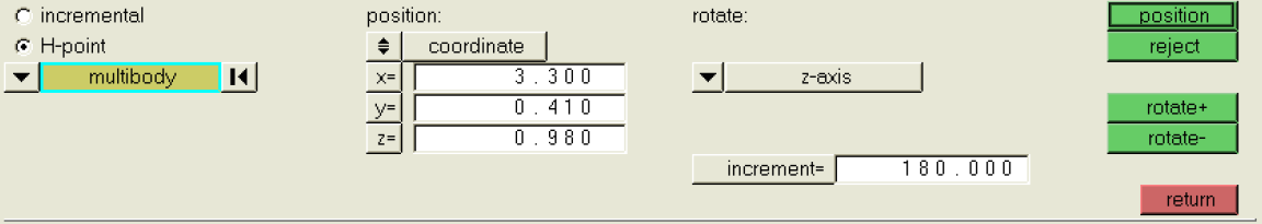
Figure 1.
Import File
In this step, you will import the file.
- Click .
- In the File: field, select the d_hyb350el_usr.xml file and click Open.
- Click Import to import the model.
Position the Dummy H-Point
In this step, you will position the dummy H-point.
Position the Dummy Limbs
In this step, you will position the dummy limbs.
You can quickly find the dummy limbs used in the steps below by using the Model Browser. Right-click on any entity and select Isolate to display only the part being manipulated.
You will use the Dummy Positioning panel for this step.
-
Rotate the femur ellipsoids.
- Rotate the upper tibia.
- Rotate the upper arm.
-
Rotate the lower arm.
- Select the left lower arm ellipsoid (ArmLowL_bod).
- In the x rot row, set the current field to -5 and click Enter.
- In the y rot row, set the current field to -70 and click Enter.
- Select the right lower arm ellipsoid (ArmLowR_bod).
- In the x rot row, set the current field to 5 and click Enter.
- In the y rot row, set the current field to -70 and click Enter.
- Remain in the Dummy Positioning panel.
Set the Steering Wheel Tilt
In this step, you will set the tilt of the steering wheel.
Define the MADYMO/SYSTEM/FE MODEL Hierarchy
In this step, you will define the MADYMO/SYSTEM/FE MODEL Hierarchy.
- Click on the Model Browser.
- Drag and drop truck_system and steering_system from ASSEMBLY.MADYMO and ASSEMBLY.MADYMO.1 respectively into the ASSEMBLY.MADYMO.2 folder.
- Right-click and select delete on ASSEMBLY.MADYMO and ASSEMBLY.MADYMO.1.
Apply a Pulse Function
In this step, you will apply a pulse function.
Apply Gravity
In this step, you will apply gavity using a gravity vector.
Define Contacts
In this step, you will define the Contacts using the contacts panel.
-
Create a contact entity.
- Click .
- In the name= field, enter seat_to_dummy.
- Click type= and select MB_MB from the pop-up list.
- Click create/edit to create the entity and bring up the Card Editor.
-
Define contact attributes.
- In the FRIC_COEF field, enter 0.1.
- Click on the box under CONTACT_TYPE and select MASTER from the pop-up list.
- Click return to save the changes and close the Card Editor.
-
Add master and slave surfaces.
- Click add to open the add subpanel.
- Next to the master: field, click the yellow sets entity selection box twice to bring up a list of sets.
- Activate the check box next to seat_gmb to make seat_gmb the master surface.
- Click select.
- Click update to the right of master: to update the master surface definition.
- Next to the slave: field, click the yellow sets entity selection box twice to bring up a list of sets.
- Activate the checkbox next to thorax_gmb and pelvis_gmb to use these as the slave surface.
- Click select.
- Click update to the right of slave: to update the slave surface definition.
- Repeat steps 1 through 3.i for the other contacts.
Add Seatbelts
In this step, you will create a seatbelt system using the seatbelt routing panel.
Equivalence Duplicate Nodes
In this step, you will equivalence duplicate nodes.
Export and Run the Model
In this step, you will export and run the model.
- Right-click on the ASSEMBLY.MADYMO.2 assembly in the Model Browser and click Card Edit.
- In the card image, enter 0.05 in the TIME_END field.
- Click return to save the changes and exit the card image.
- Click .
- In the file: field, enter an .xml file name.
- Click Export.