HM-4800: Setup a Permas Analysis
In this tutorial, you will complete the full setup of a Permas analysis.
Load the Permas User Profile
In this step, you will load the Permas profile in HyperMesh.
- Start HyperMesh Desktop.
- In the User Profiles dialog, set the user profile to Permas.
Retrieve and View the Model File
In this step, you will open the model file and view it in HyperMesh.
-
Open a model file by completing one of the following options:
- Click from the menu bar.
- Click
 on the Standard
toolbar.
on the Standard
toolbar.

Figure 1.
Create a Permas $COMPONENT and $SYSTEM
In this step, you will create a component and system card in HyperMesh.
-
In the Card Image dialog, click
COMPONENT.

Figure 2.
Create a Component Collector
In this step, you will create a new component collector.
-
In the Model Browser, right-click and select from the context menu.

Figure 3.A new component opens in the Entity Editor. -
Define the component properties in the Entity Editor.
-
Set card image to
<None>.

Figure 4.
-
Set card image to
<None>.
Organize the Elements
In this step, you will organize the elements of the model.
-
Select one element on one side of the clamp as seen in Figure 5.
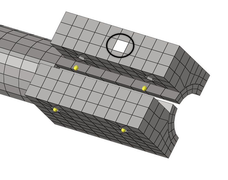
Figure 5. -
In the Organize panel, click .

Figure 6.The entire side of the clamp becomes selected as seen in Figure 6. -
Repeat steps 2
and 3 to select
the elements on the other side of the clamp.
The other side of the clamp becomes selected as seen in Figure 7.

Figure 7. - Click move.
-
Define the misc1 properties in the Entity Editor.
-
Click the color box, and select a new display
color for the component.

Figure 9.
-
Click the color box, and select a new display
color for the component.

Create Material and Elemental Properties
In this step, you will create a solid property and two materials for the existing elements. You will also assign the property and materials to the previously created components.
-
In the Model Browser, right-click and select from the context menu.
A new property opens in the Entity Editor.
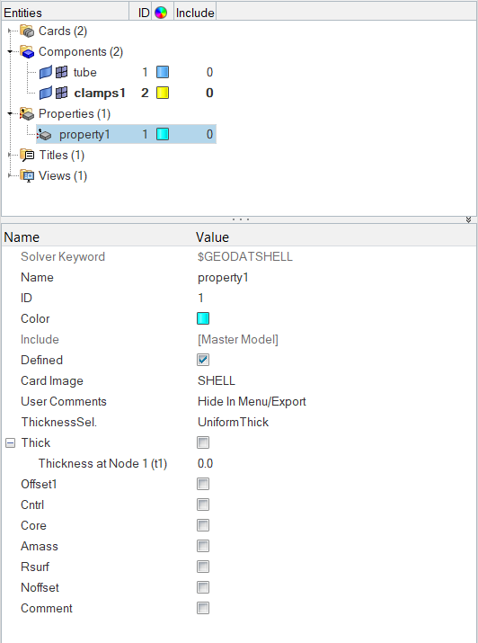
Figure 10. -
Define the property properties in the Entity Editor.
- For Name, enter Solid.
- Set card image to SOLID.
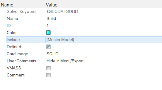
Figure 11. -
In the Model Browser, right-click and select from the context menu.
A new material opens in the Entity Editor.

Figure 12. -
Define settings in the card image.
-
In the nu field, enter 0.3.

Figure 13.
-
In the nu field, enter 0.3.
-
In the Model Browser, right-click and select from the context menu.
A new material opens in the Entity Editor.

Figure 14. -
Define settings in the Card Image dialog.
-
In the nu field, enter 0.330.

Figure 15.
-
In the nu field, enter 0.330.
-
On the Collectors toolbar, click
 .
The Components panel opens.
.
The Components panel opens. -
Click select.
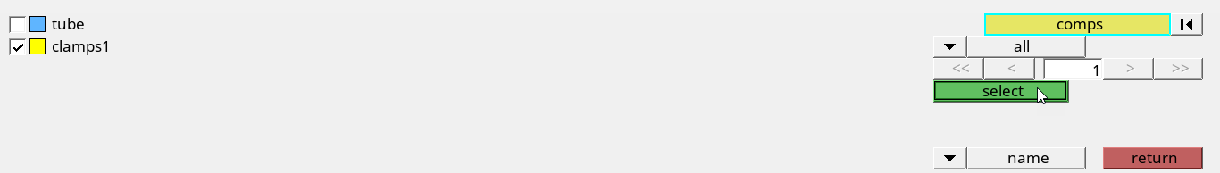
Figure 16. -
Click material= and select
Mat_1.

Figure 17. -
In the Model Browser, Component folder, right-click on
clamps1 and select Card Edit
from thecontext menu.
The card image opens, and the name of the component, property, and material you assigned is shown.

Figure 18. -
Edit the tube component.
-
On the Collectors toolbar, click .
The Components panel opens.
-
On the Collectors toolbar, click
Create Beam Elements
In this step, you will create beam elements and assign a property to individual elements during creation.
-
Define the component properties in the Entity Editor.
- For Name, enter Beam.
- Set card image to <None>.

Figure 19. -
Define the property properties in the Entity Editor.
- For Name, enter XBA.
- Set card image to BEAM.

Figure 20. -
In the card image, enter the following
parameters:
- For A-1, enter 12.6.
- For Ixx-1, enter 12.6.
- For Iyy-1, enter 12.6.
- For J-1, enter 25.1.

Figure 21. -
Set the orientation selector to z-axis.
Note: Because HyperMesh is a generic preprocessor, you have to provide an orientation vector to create the element, although this vector does not go anywhere in the Permas deck. For beams, use the node option in the same panel where a direction vector needs to be defined.

Figure 22. -
Using the node A selector, select the node on the top of one side of the clamp
as seen in Figure 23.
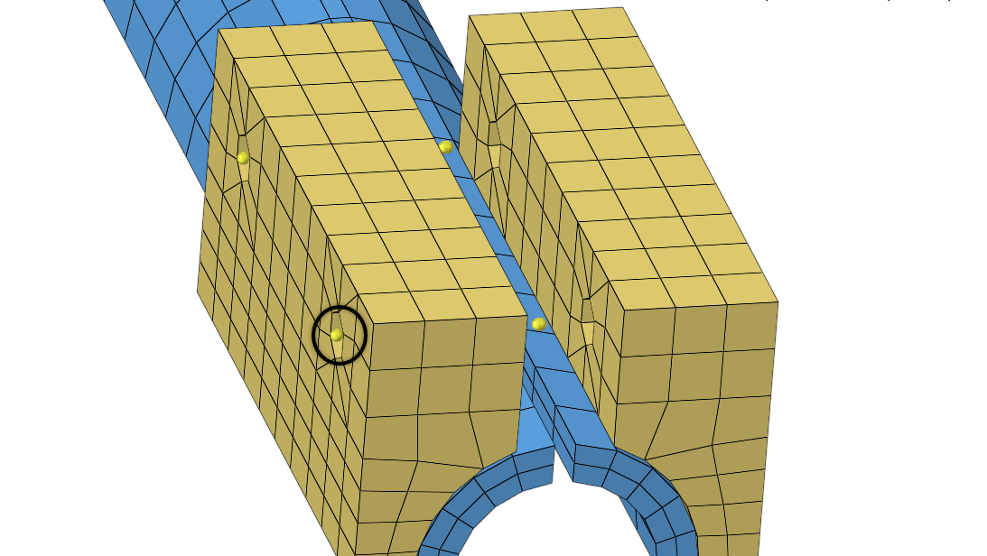
Figure 23. -
Using the node B selector, select the node in the middle of the clamp that is
closest to the node you selected as node A as seen in Figure 24.
Tip: You may need to zoom in on the model to properly select the the node in the middle of the clamp which is closest to the node you selected as node A.
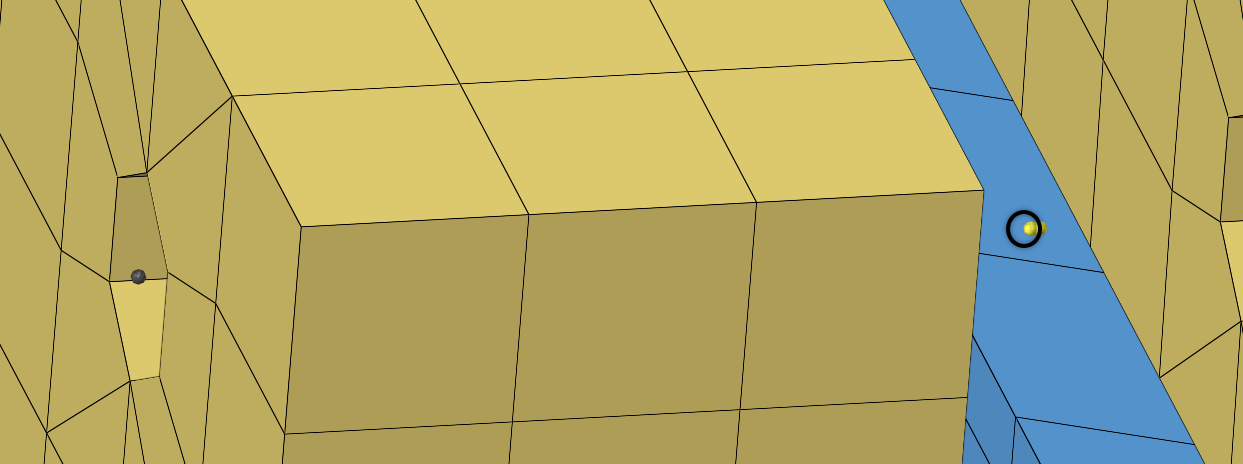
Figure 24.The beam is created automatically. -
In the Model Browser, Component folder, right-click on
clamps1 and select Hide from
the context menu to see the four sets of bars connecting
the six nodes.

Figure 25. -
In the Model Browser, click
 to
display the elements in the color of the property that has been assigned to
them.
Tip: This is a good way to ensure that you have assigned the correct property to the elements.
to
display the elements in the color of the property that has been assigned to
them.
Tip: This is a good way to ensure that you have assigned the correct property to the elements.
Figure 26. -
In the Model Browser, click
 to return
to the default display settings.
to return
to the default display settings.
- Optional: If necessary, right-click on the clamps1 component and select Show to display the clamps again.
Create a Spring Element
In this step, you will create a spring element and change the element type used when elements are created. You will also use the coincident picking mechanism to help you precisely select nodes.
-
Define the component properties in the Entity Editor.
- For Name, enter Springs.
- Set card image to PART_ELPROP.

Figure 27. -
Define settings in the card image.
-
In the DOF1 and DOF2 fields, enter 2.

Figure 28.
-
In the DOF1 and DOF2 fields, enter 2.
-
Open the Springs panel by doing one of the following:
- Open the ID page and then selecting
springs.
 Figure 29.
 - Click from the menu bar.
- Open the ID page and then selecting
springs.
-
Using the node selector, select the node shown in Figure 30.
The coincident picking tool appears, and displays two nodes.

Figure 30. -
Click the top node displayed by the coincident picking tool as seen in Figure 31.

Figure 31. -
Using the coincident picking tool, click the bottom node as seen in Figure 32.

Figure 32. -
Repeat steps 16
through 19 to
create a spring on the other side of the model.

Figure 34.

Create Multi-Point Constraints
In this step, you will create two different types of multi-point constraints (MPCs). You will also create a component collector for each type of MPC so you can switch their display on and off separately.
-
Clear the dof4, dof5 and
dof6 checkboxes.
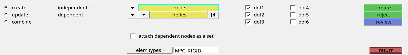
Figure 36. -
Using the independent node selector, select one of the nodes at the end of the
beam elements that were created in Create Beam Elements.
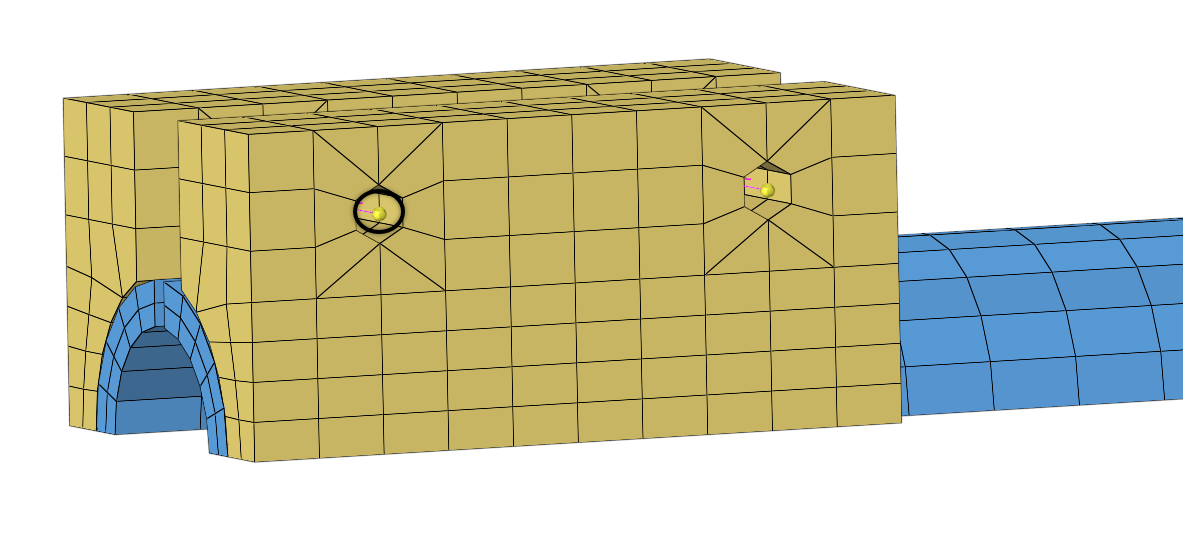
Figure 37. -
Using the dependent node selector, select the nodes surrounding the first node
as seen in Figure 38.

Figure 38. -
Click create.
HyperMesh generates the MPC.

Figure 39. -
Using the independent node selector, select the inner end of one of the beams
created in Create Beam Elements.

Figure 40. -
Using the dependent node selector, select the inner end of the other
beam.
The MPC Same rigid is created.

Figure 41.
Set Definition
In this step, you will create sets that will later be used for contact definition.
-
In the Model Browser, Views folder, right-click on
set_def and select Show from
the context menu.
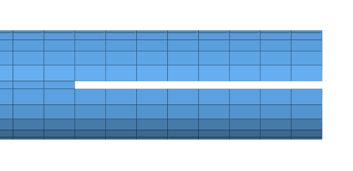
Figure 42. - Define the set within the Create set dialog.
-
On the Standard Views toolbar, click
 .
.


Create Surfaces from Solid Elements
In this step, you will create surfaces from solid elements.
-
Set the switch to elems.

Figure 45. -
Using the nodes selector, select two nodes on the tube component.
Tip: These nodes should be on one solid element, diagonal from each other.These nodes will be used to specify the faces of the solids to be taken into account for this surface creation.

Figure 46.
Define the Contact Partners
In this step, you will define the contact partners using $CONTACT.
| Contact Name | Type | Master | Slave |
|---|---|---|---|
| Bolt_1 | Node to Node | SET_11 | SET_12 |
| Bolt_2 | Node to Node | SET_21 | SET_22 |
| Gap | Node to Node | SET_1 | SET_2 |
| Tube_clamps | Surface to Node | Surf_Tube | Clamps |
-
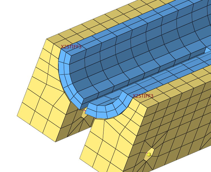
Click review.
You should now be able to see if you have set up master and slave surfaces correctly for your contact definition. Master surfaces display in blue, and slaves display in red. If one (or both) do not display, then you might have missed clicking update. If this happens, select the missing entity (master or slave) again and click update.

Figure 47. -
Rotate the model to view the interface.

Figure 48. -
Create the Bolt_2 interface using the following criteria:
- Set Interface type to CONT_NODE_NODE.
- Set Master set to SET_21.
- Set Slave set to SET_22.

Figure 49. -
Isolate the display of the tube component and create the Gap interface using
the following cirteria:
- Set Interface type to CONT_NODE_NODE.
- Set Master set to SET_1.
- Set Slave set to SET_2.

Figure 50. -
In the card image of the $CONTACT card, click
CONTSYS and select
DIRECT.

Figure 51.
Create the Boundary Conditions
In this step, you will create constraints and group them into one load collector. You will also create a $CONSTRAINTS variant (load step in HyperMesh) and attach the load collector with the previously created contact constraints.
-
On the Standard Views toolbar, click .
-
While pressing Shift, draw a box
around the bottom row of elements to select the nodes.

Figure 52. -
Right-click on the nodes around the MPC Rigids to deselect them.

Figure 53. -
While pressing Shift, draw a box
around the far end of the tube to select those nodes in order to include them in
the constraint.

Figure 54. -
Select three nodes on the narrow edge of the tube, and then click
select entities.
All of the nodes on that plane highlight.

Figure 55.
Assign the Boundary Conditions to a Load Step
In this step, you will assign the boundary conditions to a load step.
Define the Load Collector and Contact Property
In this step, you will create one load pattern (LPAT) for a force applied to the tip of the tube as well as the contact properties for the contacts.
-
Using the nodes selector, select the node.

Figure 56. -
In the ContactForce(1) field, enter 10000.

Figure 57.
Define the $NLLOAD Cards
In this step you will create a $NLLOAD card to specify how individual load patterns are acting over an artificial time.
-
Define settings in the card image.
-
Enter the information for each of the load patterns.
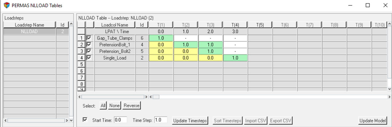
Figure 58.
Note: Time values should be between 0 and 1. -
Enter the information for each of the load patterns.
Define the $SITUATION Card
In this step, you will build a $SITUATION card which specifies which loads, boundary conditions, and system definitions are combined for this analysis.
- Open the Load Steps panel.
- In the name field, enter SIT_NLLOAD.
- Click create.
- Click edit to open the card image.
-
Define the card image settings.
- Set AnalysisProcedure to SITUATION.
- Using the CONSTRAINTS selector, select Con_1.
- Using the LOADING selector, select NLLOAD.
- Click return twice to close the card image and the panel.
Export the Deck
In this step, you will export the deck as a .dat file.
-
Next to Export Options, click
 .
.
Acknowledgements
Altair thanks INTES for their assistance and support during the creation of this tutorial.