HM-4700: Using the PAM-CRASH 2G Interface in HyperMesh
In this tutorial, you will: create Control Cards, boundary conditions, time histories, functions, and sensor cards; define materials, HyperMesh groups, and rigid walls; assign element types; and export a PAM-CRASH 2G data deck.
Before you begin, copy the rail-dyna.hm file from <hm.zip>/interfaces/pamcrash/ to your working directory.
Also, it is recommended that you complete the introductory tutorial, HM-1000: Getting Started with HyperMesh.
Load the PAM-CRASH User Profile
In this step, you will load the PAM-CRASH profile in HyperMesh.
-
Set the subprofile to Pamcrash2G2012.
Selecting the PAM-CRASH user profile and the Pamcrash2G2012 subprofile sets the FE input reader to PAM-CRASH 2G and loads the PAM-CRASH 2G 2012 FE output template. It also loads the PAM-CRASH 2G Utility menu, which contains numerous tools specific to this interface. The graphical user interface is tailored to PAM-CRASH 2G users.
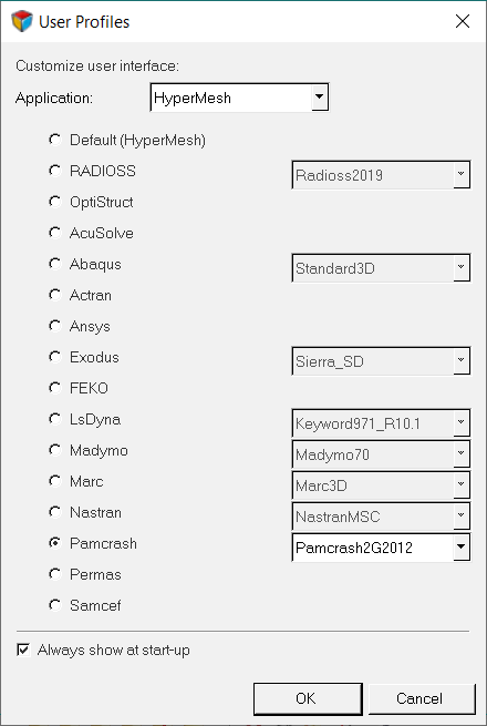
Figure 1.
Retrieve and View the Model File
In this step, you will open the model file and view it in HyperMesh.
-
Open a model file by completing one of the following options:
- Click from the menu bar.
- Click
 on the Standard
toolbar.
on the Standard
toolbar.
- In the Open Model dialog, open the rail-dyna.hm file.
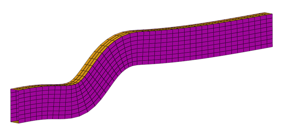
Figure 2.
Create Control Cards
In this step, you will create Control Cards for PAM-CRASH 2G.
-
Define the title card.
-
In the TITLE field, enter This is my first PAM-CRASH
example.
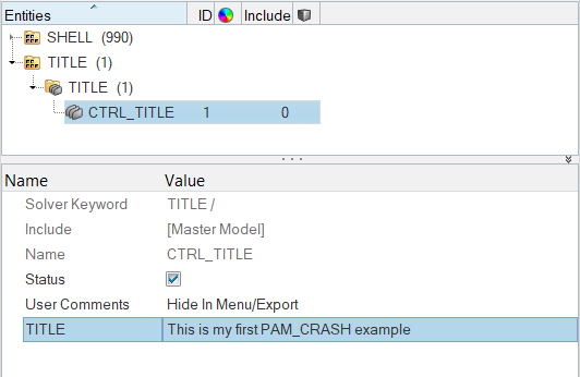
Figure 3.
-
In the TITLE field, enter This is my first PAM-CRASH
example.
-
Create and define the output Control Cards.
-
For VALUE, under THPOUTPUT_OPT, enter
0.005.
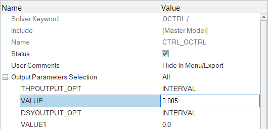
Figure 4. -
For TIO2, enter 0.06.
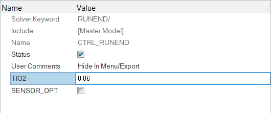
Figure 5.
-
For VALUE, under THPOUTPUT_OPT, enter
0.005.
-
Define the file optional keyword.
-
For NAME, enter rail-dyna.hm.
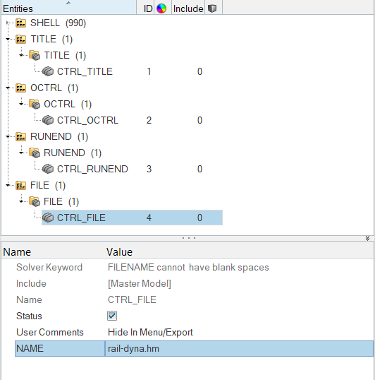
Figure 6.
-
For NAME, enter rail-dyna.hm.
-
Define the time step optional keyword.
-
Set TIMESTEP_OPT_BN to BEND.
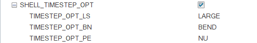
Figure 7.
-
Set TIMESTEP_OPT_BN to BEND.
Assign Element Types
In this step, you will assign element types for PAM-CRASH 2G.
Depending on the analysis requirement, the HyperMesh basic element type can be changed.
For example, a quad4 can be a SHELL or a MEMBR element. The tria3 element can be a TRIA_C, SHELL, or MEMBR element. The tetra4, the penta6, and the hexa8 elements define the SOLID elements of PAM-CRASH. Properties can be added for the selected element type using Control Cards.
- Open the Element Type panel by clicking from the menu bar.
- Open the 2D & 3D subpanel.
- Click quad4 = and select SHELL.
- Click .
- Click update.
- Click return to exit the panel.
Define a Material and /PART Cards
In this step, you will define a material and /PART cards for PAM-CRASH 2G.
-
Rename the tmp component.
-
In the Model Browser, Component folder, select the
tmp component.
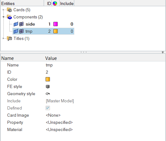
Figure 8.The Entity Editor opens, and displays the component's card data.
-
In the Model Browser, Component folder, select the
tmp component.
-
Create and define a type 102 material .
-
Assign a material and thickness to the side and topbottom collectors.
-
In the Model Browser, Component folder, select
side and
topbottom.
The Entity Editor opens and displays the selected component's common card data.
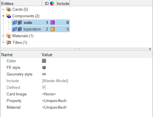 Figure 9.
-
In the Model Browser, Component folder, select
side and
topbottom.
Define HyperMesh Groups
In this step, you will define HyperMesh groups: sliding interface for PAM-CRASH 2G.
This step describes how to define a type 36 self contacting sliding interface. A second interface is defined only for tutorial purposes.
-
Define the group.
-
In the Solver Browser, right-click and select from the context menu.
A new group opens in the Entity Editor.
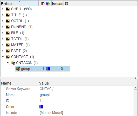
Figure 10.
-
In the Solver Browser, right-click and select from the context menu.
-
Add the slave components.
In this step, the Entity Editor should be open for the self_impact group.
-
Set the entity selector to Components.
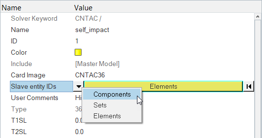
Figure 11. -
In the Select Components dialog, select
side and topbottom and
then click OK.
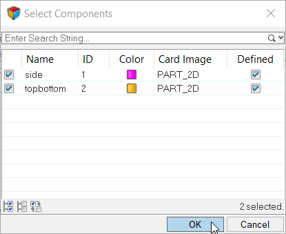
Figure 12.
-
Set the entity selector to Components.
-
Define an additional contact.
This procedure explains how to define a type 34 master slave (element - node) contact.
-
In the Solver Browser, right-click and select from the context menu.
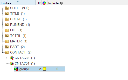
Figure 13.A new group opens in the Entity Editor.
-
In the Solver Browser, right-click and select from the context menu.
-
Add the master elements and slave nodes.
In this step, the Entity Editor should be open for the masterslave group.
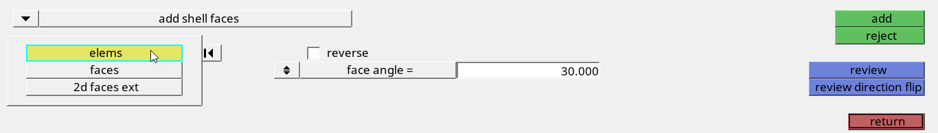
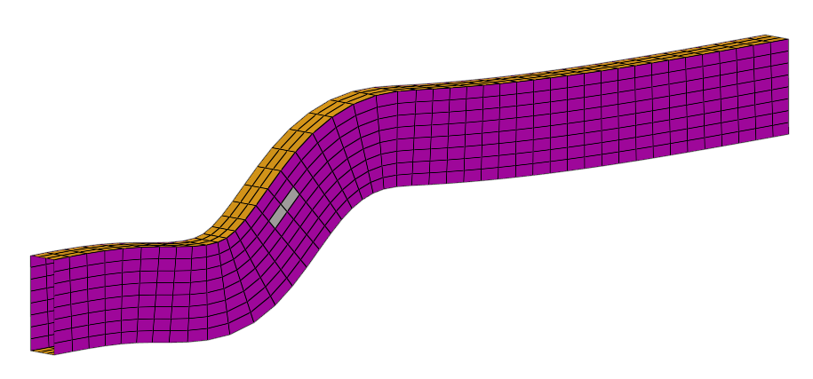

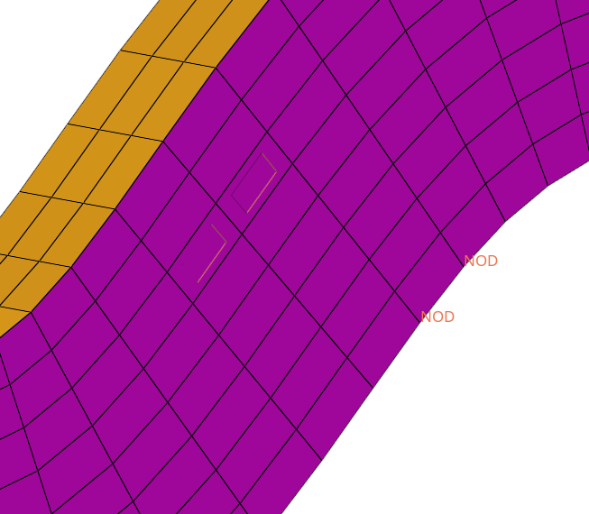
Figure 17.
Define a Rigid Wall
In this step, you will define a rigid wall for PAM-CRASH 2G.
-
Create a base node for the rigid wall.
- Click create.
-
Create and define the rigid wall card.
-
In the size =, enter 100.
The display size of the rigid wall is specified.
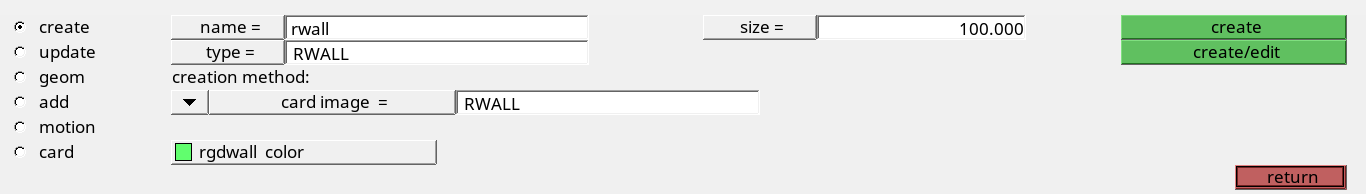
Figure 19.
-
In the size =, enter 100.
-
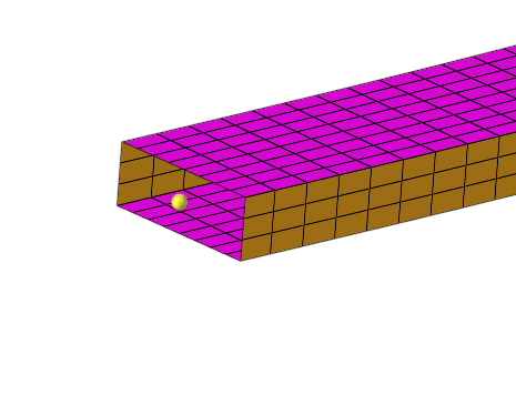
Define rigid wall geometry.
-
Click the second switch and select x-axis.
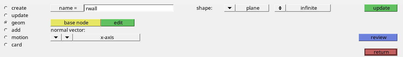
Figure 20. -
Click update.
The rigid wall displays as seen in Figure 21.
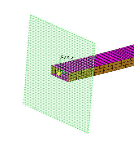
Figure 21.
-
Click the second switch and select x-axis.
-
Add secondary nodes for the rigid wall.
-
In the id field, enter 1-21 and then press
ENTER.
21 nodes at the interface of the rail and the rigid wall highlight. One of the nodes is not selected.
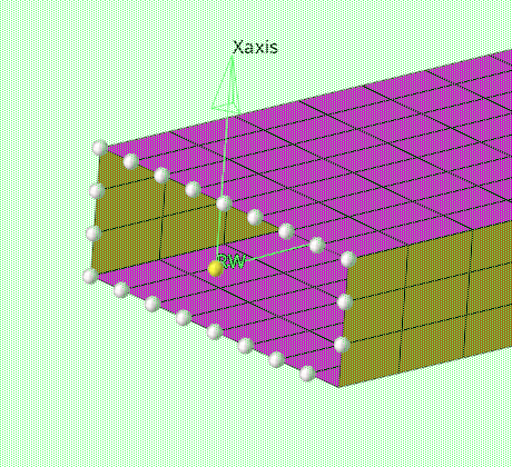
Figure 22. -
Click add.
The selected nodes are now set as secondarys.
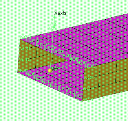
Figure 23.
-
In the id field, enter 1-21 and then press
ENTER.
-
Add motion to the rigid wall.
-
Set type of motion to velocity.
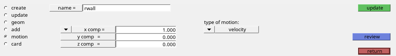
Figure 24.
-
Set type of motion to velocity.
Define Attributes in the Card Previewer
In this step, you will define attributes in the card previewer.
Create Boundary Conditions
In this step, you will create model boundary conditions for PAM-CRASH 2G.
-
Create a load collector.
-
Specify the constraints.
-
Press ENTER.
22 nodes highlight.
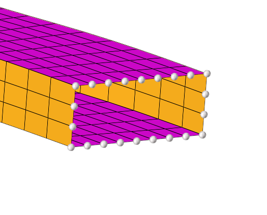
Figure 25. -
Click create.
Constraints are now added to the selected nodes.
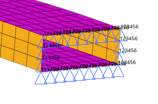
Figure 26.
-
Press ENTER.
Create Time Histories
In this step, you will create time histories for PAM-CRASH 2G.
-
Create a node time history card.
-
Create an element time history card.
- In the name field, enter elem_thp.
- Set the entity selector to elems.
- Select a few elements.
- Click create.
-
Review time histories entities.
-
View the time history card image.
Create a Function
In this step, you will generate a curve and a function.
-
In the y = field, enter {1, 0, 0}.
Tip: Include the brackets in the x = field.
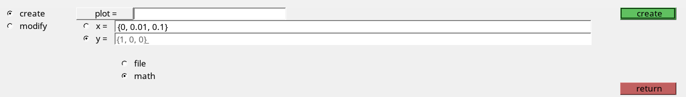
Figure 27. -
Click create.
HyperMesh generates a curve.
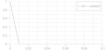
Figure 28.
Create a Sensor Card
In this step, you will create a sensor card.
Export a Data Deck
In this step, you will export a PAM-CRASH 2G data deck from HyperMesh.