HM-4200: Set Up Nastran Static Analysis in HyperMesh
In this tutorial, you will learn how to define a model in HyperMesh, apply boundary conditions in HyperMesh, write the Nastran input deck, and view the results.
Load the Nastran User Profile
In this step, you will load the Nastran profile in HyperMesh.
- Start HyperMesh Desktop.
- In the User Profile dialog, set the user profile to Nastran.
Retrieve and View the Model File
In this step, you will open the model file and view it in HyperMesh.
-
Open a model file by completing one of the following:
- Clicking from the menu bar.
- Clicking
 on the Standard
toolbar.
on the Standard
toolbar.
-
In the Open Model dialog, open the
plate_hole.hm file.

Figure 1.
Create Material Collectors and Components
In this step, you will create material collectors and components in HyperMesh.
-
In the Model Browser, right-click and select from the context menu.
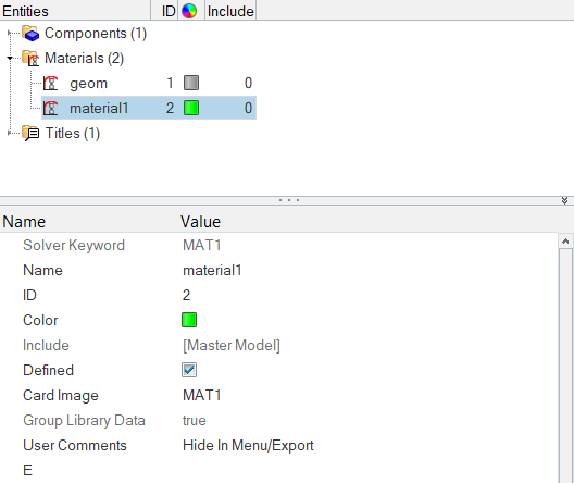
Figure 2.A new material opens in the Entity Editor. -
In the Model Browser, right-click and select from the context menu.
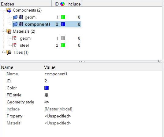
Figure 3.A new component opens in the Entity Editor. -
Right-click on Property and select
Create from the context menu.
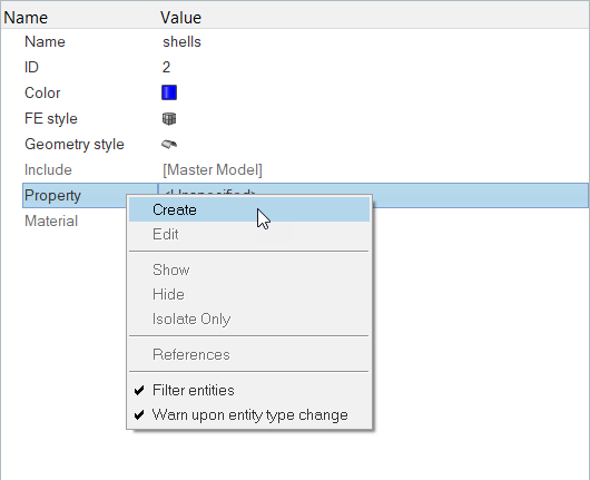
Figure 4. -
Click Close.
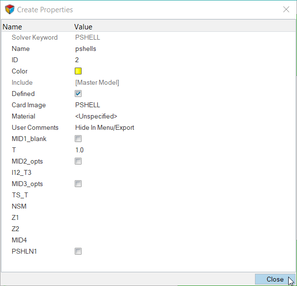
Figure 5.HyperMesh assigns the property pshells to the component shells. -
For Material, click .
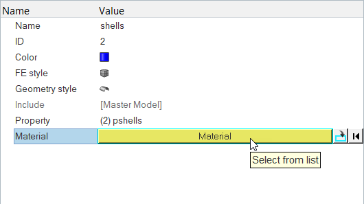
Figure 6. -
In the Select Material dialog, select
steel and then click OK.
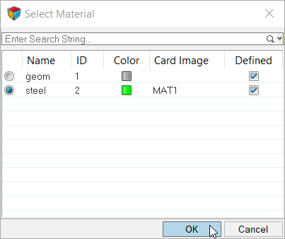
Figure 7.HyperMesh assigns the material steel to the component shells.
Mesh the Geometry
In this step, you will mesh the geometry using the Automeshing panel.
-
Click mesh.
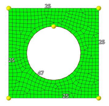
Figure 8.HyperMesh meshes the selected surfaces, and the meshing module opens.
Apply Boundary Conditions to the Model
In this step, you will create collectors, constraints, and forces in order to apply boundary conditions to the model.
-
Create collectors.
Load collectors are created before boundary condition and loads. These load collectors are used for boundary conditions and loads.
-
In the Model Browser, right-click and select from the context menu.
A new load collector opens in the Entity Editor.
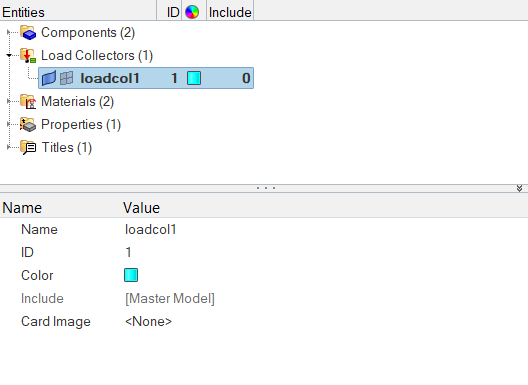
Figure 9. -
For Name, enter forces.
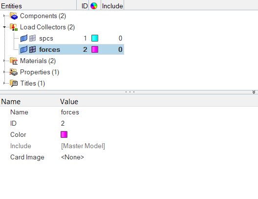
Figure 10.
-
In the Model Browser, right-click and select from the context menu.
-
Create constraints.
-
Draw a box around all of the displayed nodes while excluding the four
corners of the model.
Tip: Since each side of the box must be drawn individually, draw the box by selecting each corner as indicated in Figure 11. Select the top, right corner first and continue clockwise.
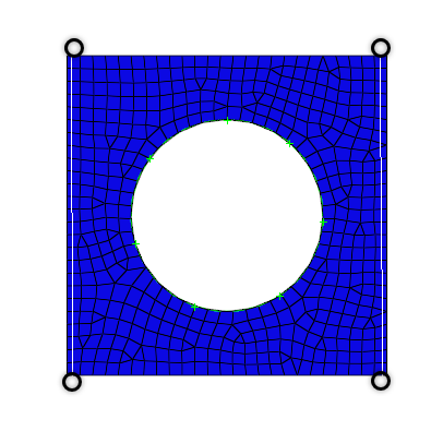
Figure 11. -
Click select entities.
HyperMesh selects all of the nodes outside of the window you drew.
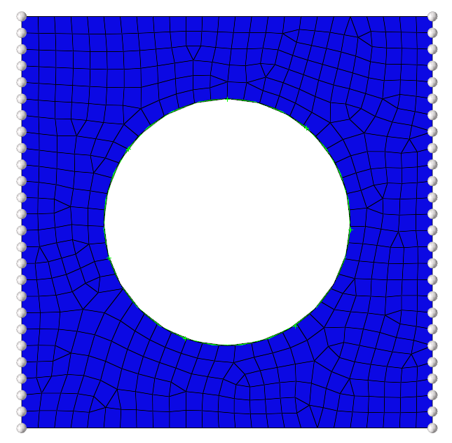
Figure 12. -
Select all of the dof (degree of freedom)
checkboxes.
Note: Dofs that are checked are constrained. Dofs 1, 2, and 3 are x, y, and z translation degrees of freedom, and dofs 4, 5, and 6 are x, y, and z rotational degrees of freedom.
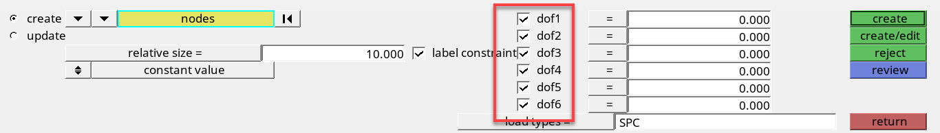
Figure 13. -
Apply these constraints to the selected nodes by clicking
create.
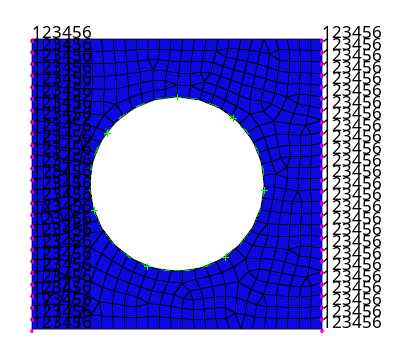
Figure 14.
-
Draw a box around all of the displayed nodes while excluding the four
corners of the model.
-
Create forces on the nodes around the hole.
-
Select all of the nodes around the hole of the model.
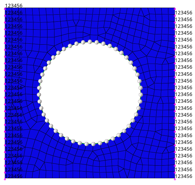
Figure 15. -
Click create.
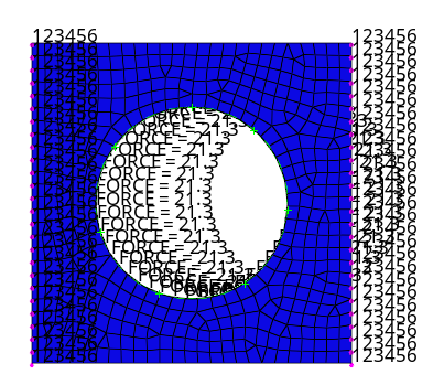
Figure 16.
-
Select all of the nodes around the hole of the model.
Create a Nastran Subcase
In this step, you will creat a Nastran subcase (a load step in HyperMesh).
-
Create the load step.
-
In the Model Browser, right-click and select from the context menu.
A new loadstep opens in the Entity Editor.

Figure 17. -
For SPC, click .
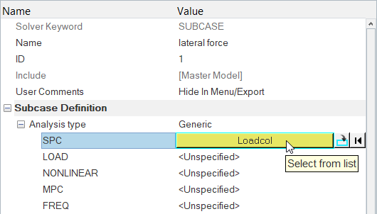
Figure 18. -
In the Select Loadcol dialog, select
spcs and then click OK.
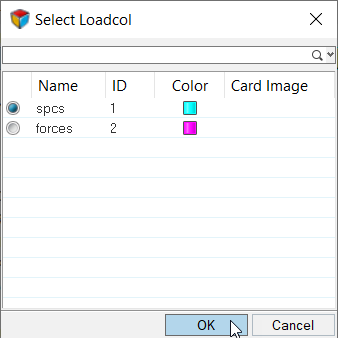
Figure 19.
-
In the Model Browser, right-click and select from the context menu.
-
Create control cards.
-
Set Analysis to Statics.
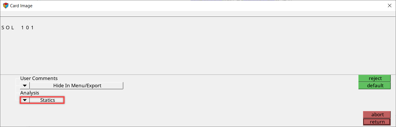
Figure 20. -
In the card edit field, click POST_V1 and enter
-2 in the editable field.
Note: This option specifies that an op2 file should be created.
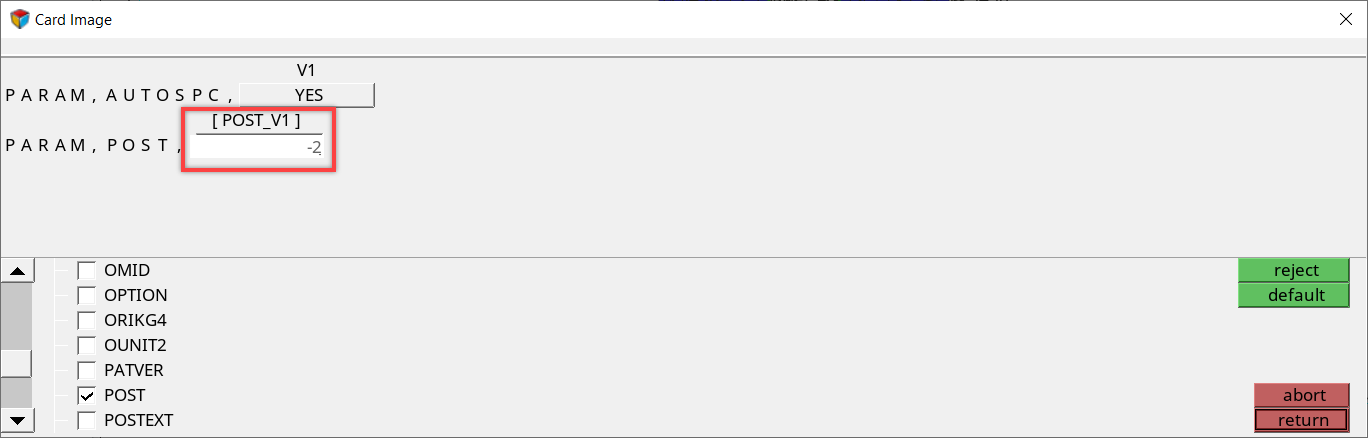
Figure 21.
-
Set Analysis to Statics.
Write the Nastran Input Deck
In this step, you will write the Nastran input deck.
-
Write your file.
-
Save your file and exit HyperMesh.
- From the menu bar, click .
- In the Save Model As dialog, navigate to your working directory and save the file as plate_hole_new.hm.
View the Results
In this step, you will view the results and the deformed shape.
-
Add a HyperView page to the session and load the
fem and op2 files.
-
On the Page Controls toolbar, click
 .
.
-
On the Page Controls toolbar, click
-
View a deformed shape.
-
View a deformed plot of your model overlaid on the original, undeformed
mesh by clicking Apply.
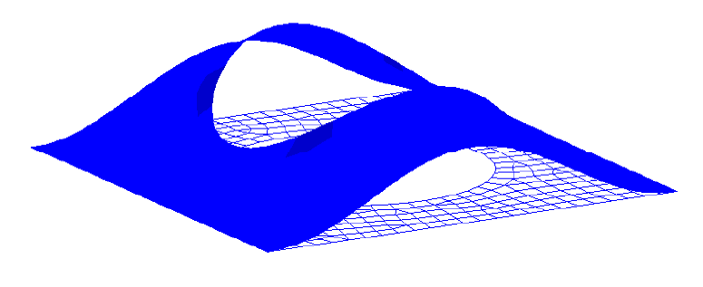
Figure 22.
-
View a deformed plot of your model overlaid on the original, undeformed
mesh by clicking Apply.
-
View a contour plot of stresses and displacements.
-
On the Standard Views toolbar, click
 .
.
-
Click Apply.
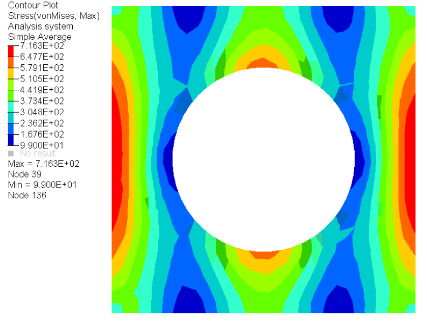
Figure 23.
-
On the Standard Views toolbar, click