HM-3320: Penetration Check
In this tutorial you will learn strategies for penetration checking.
- Checks can be run on both 2D and 3D elements, 2D elements only, or 3D elements only.
- Select include self interference to include components that bend and pass through themselves. This occurs rarely and is expensive when running the check. By default, this checkbox is cleared.
- By default the check is set to all interferences, meaning both intersection and penetration. The intersections only option and the penetrations only option are also available.
- Select allowable interference depth to ignore penetrations and intersections that are less than the value specified. By default, this checkbox is cleared.
- Select uniform thickness to assign a global thickness to all components.
- Select thickness multiplier to multiply the existing thicknesses in the model.
When the penetration check is invoked, a new penetration tab opens in the browser area.
The results are split into intersections and penetrations with the number of components that are clashing in brackets. In the example below, two components are intersecting and eleven components have material penetration. Expand each section for more detail as to which components have failed.
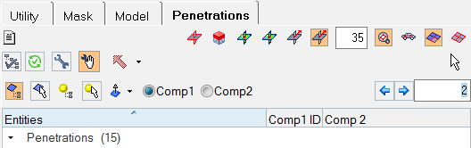
Figure 1.
The fixing of penetrations and intersections falls into two categories: automatic and manual. These capabilities will be discussed in more detail in the tutorial.
Open the Model File
In this step you will open the model file, penetration_check.hm.
-
On the Visualization toolbar, click
 to shade the model's elements and mesh lines.
Run the Penetration Check
In this step you will run the penetration check.
-
In the Selection field, click the entry 0 Components and
then click Components again.
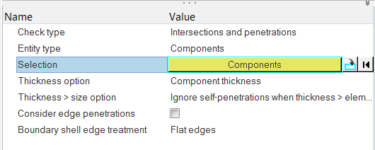
Figure 2. -
At the bottom of the Select Components dialog, click
Select All and then click the OK button.
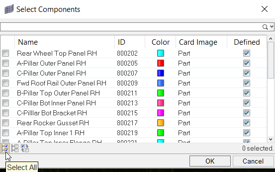
Figure 3. -
Back in the Entity Editor, click the
Check button.
Once the check is complete, the Penetration tab populates with one intersection and 15 penetrations.
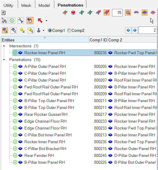
Figure 4.
Review the Intersection Results
In this step you will review the intersection results.
-
View intersections by expanding Intersections in the Penetration tab, if there
are more than one.
Note: Based on which mode is chosen, certain components are displayed on the screen.
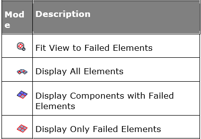
Figure 5. -
Select
 (Display Components with Failed Elements) and
 (Fit View to Failed Elements).
-
Under Intersections, select the Rocker Inner Panel RH
component.
HyperMesh automatically fits the screen to the failed intersecting elements.
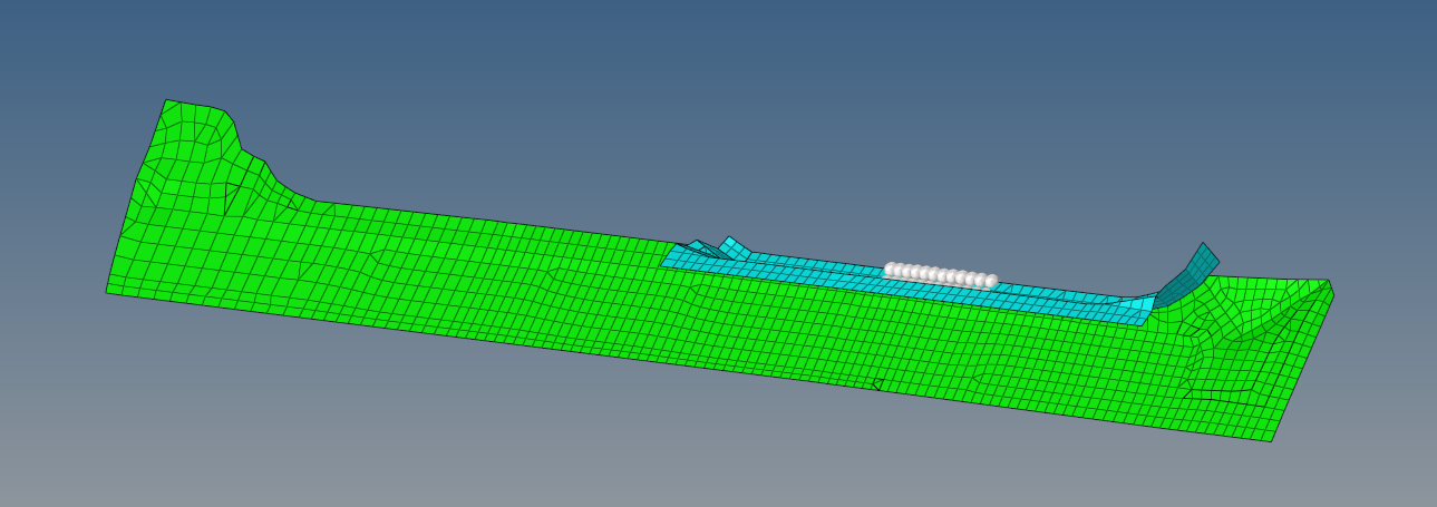
Figure 6. -
Review other visualization modes by clicking
 (Review Failed Elements). The contour and vector
displays are only applicable to intersections. The intersecting elements display
as follows:
(Review Failed Elements). The contour and vector
displays are only applicable to intersections. The intersecting elements display
as follows:
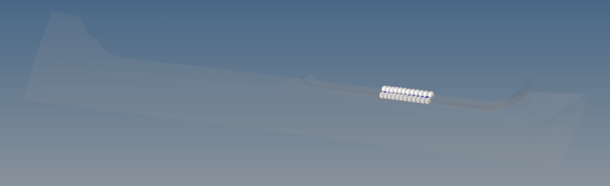
Figure 7.
Fix Intersection Results
In this step you will fix the intersection results.
To fix intersections manually:
-
Ensure that the intersecting entities can be fixed by clicking
 (Manual Fix Tools).
Note: Additional tools display for intersection fixing.
(Manual Fix Tools).
Note: Additional tools display for intersection fixing. -
Click
 (Elements from Tree Selection).
Note: You will not pick any additional elements.
(Elements from Tree Selection).
Note: You will not pick any additional elements. -
Click
 (Move in Normal Direction) for the direction of
movement.
(Move in Normal Direction) for the direction of
movement.
-
For the distance value, type 2.
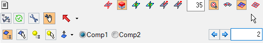
Figure 8. -
Click
 twice.
HyperMesh moves the selected elements in the chosen direction.Note: After the elements have been moved by a value of 4, they no longer intersect.
twice.
HyperMesh moves the selected elements in the chosen direction.Note: After the elements have been moved by a value of 4, they no longer intersect. -
Click
 (Recheck).
To fix intersections automatically,
-
Click the Automatic Pentration/Intersection Fix button
(
 ).
).
Interrogate the Penetration Results
In this step you will interrogate the penetration results.
-
Select the component, C-Pillar Bot Inner Panel RH. The
penetration results look similar to the following image.
Figure 9. -
View different types of display results for penetration by clicking the
following visualization options:


 .
Remember that the columns can be sorted. For example, if you were only interested in the worst offending penetrations then sorting by the depth column will reorganize the tree structure, while still retaining the parent/child relationship.
.
Remember that the columns can be sorted. For example, if you were only interested in the worst offending penetrations then sorting by the depth column will reorganize the tree structure, while still retaining the parent/child relationship.
Fix Penetration Results
In this step you will fix the penetration results.
Within the checking tool there is an automatic penetration fix that will remove the penetrations within the model. This works by physically moving the failed nodes to new locations to remove the material penetration.
In some circumstances, there may be the need to lock or freeze a component that cannot be adjusted or moved by the fixing tool. To achieve this, right-click on the component and select Lock Component from the context menu. Once a component is locked, a symbol will appear by the folder indicating that the component is locked.
In the previous example, you locked the component, C-Pillar Bot Inner Panel RH. The lock symbol appears multiple times to correspond with the multiple references to the same component. To unlock the component, right-click again on the locked component and select Unlock Component from the context menu. For the purpose of this tutorial you will not be using the lock functionality.