2D BL Meshing
2D BL meshing is a method to create a 2D mesh with or without boundary layers on planar sections defined by sets/groups of edges defining closed loops.
A region is considered closed if it is entirely bounded by edge elements (edge elements should be of type PLOTEL). Element configurations generated by 2D BL meshing are linear quadrilateral (quad4) and triangular (tria3).
Create 2D BL Mesh
Mesh 2D planar areas with boundary layers.
Restriction: Only available in Engineering Solutions when the CFD user profile is
loaded.
-
In the Default Value fields, enter the default values that apply to most
components.
-
For Bound Type, select a boundary layer type.
Choose Wall to generate boundary layers along the component edges. No boundary layers are generated when Bound Type is set to Farfield, In/Outlet, and Symmetry.Note: Edge elements in collectors having Bound Type defined as Farfield, In/Outlet, and Symmetry will be used to define the geometry, but they will not dictate element size/density.
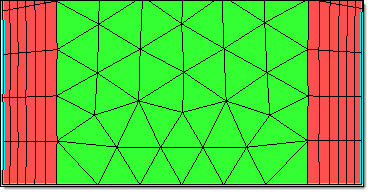
Figure 1.
-
For Bound Type, select a boundary layer type.
-
Click Add collector to select or add components containing edge elements (elem
type PLOTEL) that define the boundaries of the 2D section.
Default values (1st Layer Thickness, Growth Rate and Bound Type ) are assigned to the selected components.
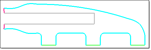
Figure 2. -
To control the aspect ratio of boundary layer elements by refining the edges to
generate boundary layer elements that satisfy the Max perimeter element aspect
ratio value, select the Allow boundary node insertion
checkbox.
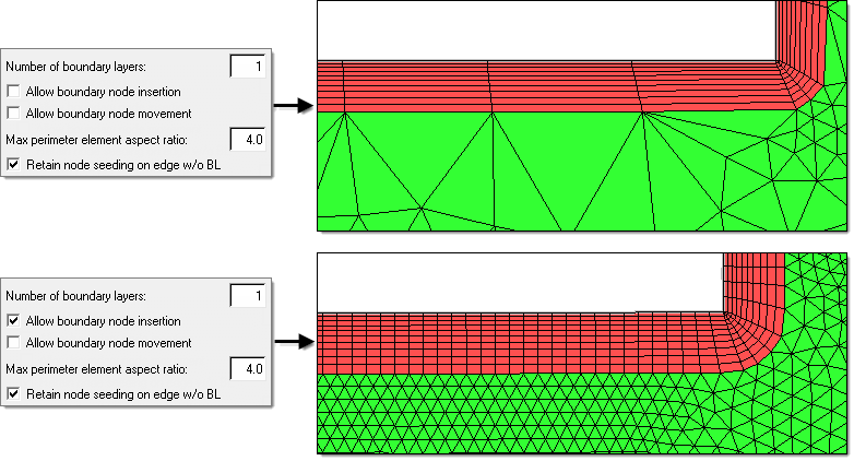
Figure 3. -
To control the aspect ratio of boundary layer elements by boundary node
movement so that generate boundary layer elements will satisfy the Max perimeter
element aspect ratio value, select the Allow boundary node
movement checbox.
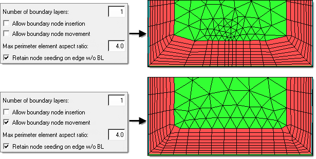
Figure 4.
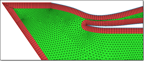
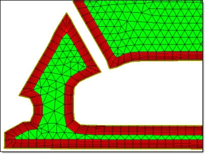
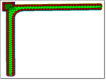
Figure 5.