Detect Holes
Locate holes in a model, and potentially all of them, define them, and add them as geometry to a new component or to the current one.
You can specify many types of criteria to define specific types of holes that you wish to find.
-
Prepare for hole detection.
-
For 3D solid hole feature detection, select a method for detecting
holes.
- Choose By specified angle to enter the exact angle of holes you wish to detect.
- Choose Auto using angle to enter upper and lower limits of hole angles that you wish to detect. Holes with feature angles beyond either of these numbers will be ignored.
Holes in 3D solids are assumed to have an opening on one or more faces of the solid. You can base detection on each hole's feature angle, that is, the angle at which the hole deviates from the face in which its opening appears.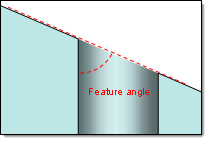
Figure 1.In either case the values must be more than zero (zero would be perfectly collinear with the face) but no greater than 90 degrees, which represents a hole that runs perfectly perpendicular to the face.
-
For 3D solid hole feature detection, select a method for detecting
holes.
-
Define the type of holes to find in 2D mesh.
-
To define a specific hole width to find, regardless of shape, select
the Minimum dimension and/or Maximum
dimension checkboxes and enter a dimension.
If set at or below zero, these checks are not run.
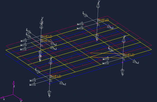
Figure 2.
All 2D holes matching the criteria are located.
-
To define a specific hole width to find, regardless of shape, select
the Minimum dimension and/or Maximum
dimension checkboxes and enter a dimension.
-
Define the type of holes to find in 3D mesh.
-
To define a specific width of the hole's opening to find, regardless of
shape, select the Minimum dimension and/or
Maximum dimension checkboxes and enter a
dimension.
This carries over from the 2D tab because the openings themselves are 2D edges. If set at or below zero, these checks are not run.
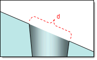
Figure 3. -
To define the depth of the hole, regardless of shape, select the
Minimum height and/or Maximum
height checkboxes and enter a height.
If set at or below zero, these checks are not run.
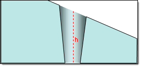
Figure 4. -
To check each node on the edge of a hole, relative to the best-fit
bounding box that encompasses all of the nodes on the hole's edge,
select the Offset plane deviation checkbox and
enter a distance measurement.
Any nodes further than this distance from the midplane of the bounding box will cause the tool to ignore the hole. If this value is set to zero or less, the check is not run at all on any holes.
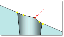
Figure 5. . With very low plane deviation, the red node might invalidate this hole. -
To search for specific tapered holes; this is the maximum angle between
the hole's sides, and a planar cross-section that is perpendicular to
its length, select the Cone angle checkbox and
enter an angle.
A value of 90 represents a hole that does not taper at all. Holes with a taper at or below the specified angle, that is, tapers sharper than the specified angle, will be found, while tapers above it, that is, closer to being a straight shaft, will be ignored. The default value is 80.0 degrees; if less than or equal to 0.0 the cone angle check is not run.
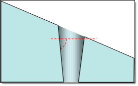
Figure 6. -
For Hole Handling, choose whether to find Open
holes, Capped holes, or
All holes.
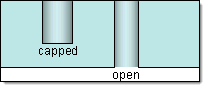
Figure 7.
All 3D holes matching the criteria are located.
-
To define a specific width of the hole's opening to find, regardless of
shape, select the Minimum dimension and/or
Maximum dimension checkboxes and enter a
dimension.