Added specific meshing tool to model engines and missiles.
Flutter Curves
Added tool to plot VG and VF (Flutter) plots from aeroelasticity flutter
analysis.
Enhancements
Support of Nastran/MSC and OptiStruct bulk data cards
FLUTTER
Define Flutter loading for flutter analysis
FLFACT
Support of Solution control
ANALYSIS = FLUTTER
AEROF
APRESS
AESYMXY
AESYMXZ
API
See the 2021.1 API Programmer’s Guide for the full list of new features and
enhancements.
Known Issues
There is a known issue with populating a custom frame over the panel area
using the hm_framework option
“drawpanel” in HyperWorks. Until the issue is
resolved, custom panel content can be posted in the tab area as a custom tab
or pop-up dialog.
Resolved Issues
hm_getvalue command was returning wrong ID value when
querying certain entity colors.
Browsers
New Features
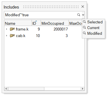
"Modified" predefined filter for Includes
"Modified" predefined filter under Includes view facilitates filtering
and finding the include files that have been modified post previous
solver deck export operation. Figure 1.
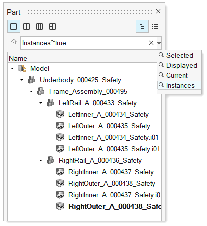
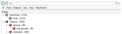
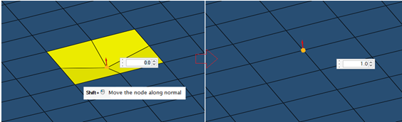
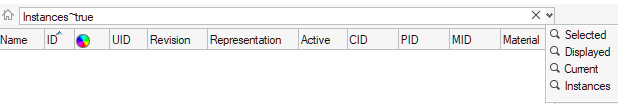
"Instances" predefined filter for Parts
"Instances" predefined filter in Part Browser
facilitates filtering all part instances. Applying the "Instances"
filter without any selection returns all part instances, while applying
the "Instances" filter by selecting a part instance returns just the
instances linked to the selected instance. Figure 2.
Enhancements
Export CSV/HTML report
Exporting of model data as a CSV/HTML report is now supported all flat
list browsers.
Select All/Reverse in browsers
Added "Select All" and "Select Reverse" context menu options in all flat
list browsers. Keyboard shortcuts "Ctrl + A" and "Ctrl + R" can also be
used to perform All and Revers selection, respectively.
Indirect to direct property conversion
Conversion of indirect property assignment to direct property assignment
is now supported for multiple component selection, even when the
selected components have different indirect properties.
Search hint in search bars
The search hint in the browser search bar now indicates the entities
that are being searched/filtered.
Find Unused/Empty entities
Unused and Empty entities can now be found by right-clicking in white
space in all the flat list browsers.
Find an attribute with empty value
All attributes with empty values can now be filtered by selecting
<Empty> as the value from suggestion
list.
Find out-of-sync revisions
All representations that are not in sync with library can now filtered
using “*” in the Revision column filter in the Part Browser.
Create Load Collector without keyword
A Load Collector without a keyword can now be created by selecting the
Collector option from the "Create" context
menu list.
Find references on nodes
Entities referenced to a node can now be queried using the
References context menu option in Nodes
view.
Delete entities from Reference Browser
Entities can now be deleted from the Reference Browser while checking references.
"Views" in Model Browser
"View" entity is now shown in the Model Browser.
Double-click on the Views folder to access the
list of views.
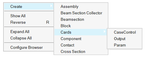
Card creation from Model Browser
In OptiStruct and Nastran interfaces, the CaseControl, Output, and
Param options under the "Create" menu are now consolidated into the
"Cards" category. Figure 3.
"Organize" to "Move to Current Include"
The "Organize" option under Includes view is relabeled as "Move to
Current Include" in all interfaces except LS-DYNA and Radioss.
Matrix Browser syncing
Table entity content is fully in sync with the Matrix Browser generated table.
Resolved Issues
Entity views are now restored on relaunch of HyperWorks.
Fixed performance issue with show/hide/isolate of components in components
view.
Fixed performance issue with moving components into assemblies.
Known Issues
Elements and nodes selected in graphics are not highlighted in browser.
Entity editor is not cleared when an entity is removed from a filtered
browser list.
Nodes are not shown in the correct include when components are dragged and
dropped across includes.
Certification
New Features
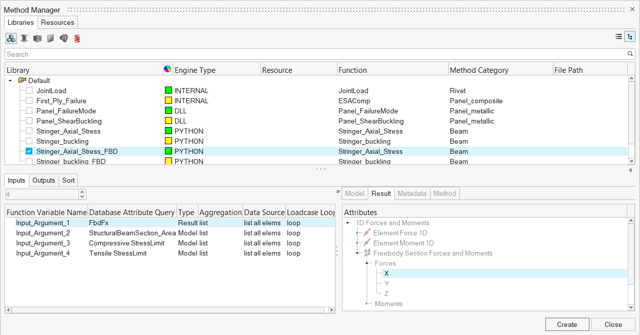
Method Manager
A new method manager UI enables you to manage methods in libraries.
Import resources (Python and Compose *.oml files).
Import a library from an *.xml file or add a new one and save to
disk.
Add and edit methods in a library with mapped arguments.
Figure 4.
The same UI is used to create designpointmethod entities in the database
from register templates.
Enhancements
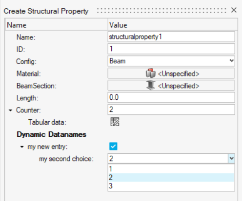
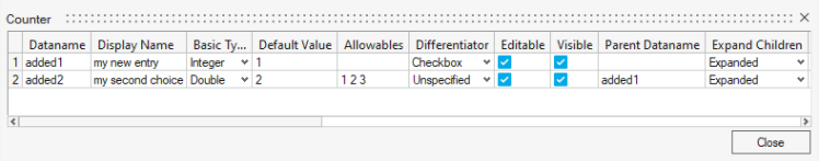
Dynamic data names
Structural property entity is enhanced with dynamic data name
support. Figure 5. Figure 6.
Each entity can be enriched with a new data name set.
New data names are saved in the HyperWorks binary file.
Data names can be accessed by certification engine as regular
data names .
Allowable are supported and rendered in entity editor as combo
box with predefined values.
Known Issues
The dynamic data names have a provision for strings but currently the engine
supports only numerical inputs.
Resolved Issues
The moment correction in the JointLoad method for rivets has been corrected
to properly account for offset in composites.
Marker plot of method results honors the displayed entities.
Envelope with “nan” values no longer returns "nan".
The Beam method named "Crippling" has been renamed “Buckling".
First_ply_failure method for composites can now run directly on
elements.
Composites
Known Issues
Performance improvements for composite ply layer and orientation
visualization.
Spreadsheet import/export - ply shape internal IDs are exported instead of
solver IDs.
Resolved Issues
Abaqus shell element orientation visualization
in Orientation Review dialog.
OptiStruct material orientation visualization in
Orientation Review dialog for PCOMPLS, PSOLID properties when
CORDM=BLANK.
Ply layer visualization will now remain on after changes to laminate.
Segmentation fault when changing ply shape from set to lines type.
Entity Editor freeze after deleting ply from composite browser.
Cleanup of spreadsheet import/export behavior in Composite Browser.
Change of symmetry option in laminate will now reflect in composite stress
toolbox for all cases.
Copy/paste not updating in composite stress toolbox in HyperWorks and swapping laminate compliance matrix
and laminate stiffness matrix.
Connectors
New Features
Stitch Connectors
A new connector type to tie Parts/Components together. There is
no realization, just the equivalencing of the nodes.
You have the option of retaining nodes and selecting the main
side of the connectors as well as the remeshing method.
xMCF File Import
XMCF 3.1 compliant.
Updated how the metadata is mapped to the connectors. The
incoming information is mapped to the metadata field on the
connector and is visible in the Entity Editor.
Attachment Workflows in Connectors (HyperWorks-Specific
New HyperWorks workflows are added
to the Connectors Ribbon. This is a direct mapping of the
Attachment workflows from the browser.
A new Attachment type is added to the Rigid Patch attachments.
This new type projects the attachment onto a plate. Figure 7.
Connector Browser
A new browser following the new paradigms from Model Browser.
The different connectors are now split into separate tabs. Figure 8.
Enhancements
Connector Group Logic
Used when dragging and dropping connectors to create a new
connector group. You are prompted to create multiple groups if
the connectors are scattered across many Subsystems. Each
connector group is then organized into a part, and the Part is
placed into the appropriate Subsystem.
If the organization is set to Automatic, and the Connector is
organized into a Subsystem different from the Subsystem the
Connector Group belongs to, the ownership of the Subsystem is
broken to ensure consistency.
Single Include for Subsystem Connectors
A single Subsystem is created for all the Subsystem connectors
to be organized into.
Organize connectors to current include
All the connectors are organized into the active include.
Seam connector Improvements
General bugfix and quality improvements.
Partial Connector realizations, allows you to define a
percentage of acceptability for the amount the connector has
successfully imprinted.
Rule Based Realizations, adjusting the HAZ lengths to try to
realize the connector automatically.
Part/Subsystem Config Improvements
Keep general connectors realized within a Subsystem when
inactive.
Prompt to realize connectors active on config change.
Link Type reacting when changing Parts/Subsystem
configurations.
Known Issues
Connector masses are no longer supported in the browser.
Resolved Issues
FE absorbing failed FEMFAT connectors.
FE absorbing of Rigid Patches over a solid holes.
FE absorbing not reading custom config file.
Duplicate Rigids when realizing bolt connectors in Abaqus user profile
FE absorbing Quad Seam issues.
End offset information is lost on positioning connector to center.
Added new configurations for Spring Bolts.
Realizing an attachment twice.
Connector groups are listed in the Model Browser.
Design Explorer
New Features
Connectors as design variables and responses
Connector attributes can now be used as design variables and as a
response. Design variables can be created directly from connector
attributes such as pitch, tolerance, or diameter. In addition, a
connector’s connector control can become a design variable, allowing
different controls to be used for a given connector within an
exploration. Finally, a new connector response, the total number of
connectors, has been provided. This response can be used as an
optimization objective to minimize the number of connectors used.
Results compare contour
A new comparison contour has been added to the Results Explorer. You can
select and compare any two runs in an exploration. The comparison plots
the difference in design variables as a bar chart and also contours the
changes onto the model graphics, allowing for easy visualization of the
design variable changes.
Machine learning enhancements
Clustering
A new AI report has been added to the Scatter Plot tool in
the Results Explorer. You can now automatically group
exploration results into clusters, classifying based on
different criteria. This can be useful in cases where you
want to view or choose designs based on a certain
classification, such as deformation mode.
Field prediction performance
Field Prediction performance has been improved so predicted
results update more quickly.
Machine learning reports on demand
AI Reports can now be run on demand. Once an exploration has
been completed, the Field Prediction and Clustering reports
can be run, even if they were not originally selected when
the exploration was originally run.
Multi-objective optimization
Optimization explorations are no longer limited to a single objective.
Multiple objectives may now be enabled for an optimization. In addition,
an Optima option has been added to scatter plots in the Results Explorer
to allow for easier viewing of the optimal runs and the resulting Pareto
front.
Additional solver support
The Design Explorer is now supported in LS-DYNA and Abaqus solver
profiles. Note that to use the Design Explorer with Abaqus requires
additional configuration. Please contact your Altair account
representative for more information.
Nominal Run shown in exploration summary tables
The nominal or baseline run is now shown for reference in exploration
summary tables. Nominal run results can be easily accessed and viewed,
and the nominal run values are available for comparison to other
exploration runs.
General
New Features
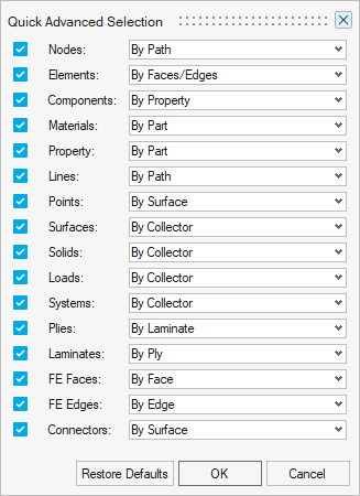
Configurable Quick Advanced Selection (Alt)
The Quick Advanced Selection keyboard shortcut (Alt) is now
configurable across many different entity types. Previously it
was only possible to use this keyboard shortcut to quickly
select Elements > By Faces & Edges, and Nodes & Lines >
By Path. Now you can use the provided configuration dialog to
associate your preferred advanced selection method to any of the
supported entity types.
All Quick Advanced Selection methods support either appending or
deselecting by using the Ctrl or Shift modifiers,
respectively.
Access the Quick Advanced Selection configuration dialog from
either Preferences > Mouse Controls, or the Right-Click > Select
menu.
Figure 9.
Face/Edge Colors
The model color controls in the View Toolbar have been split into face
& edge colors. Face color is both mesh/geometry and edge color is
the edges of those entities. The icons update based on the current
colors being displayed in the graphics.
Geometry & Mesh Visualization
A new tool to control geometry and mesh visualization of selected
components has been added to the View Toolbar. It is available under the
Show/Hide drop-down or by pressing X.
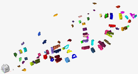
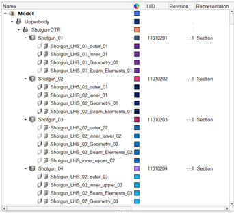
Section Library
The automotive focused section library has been added to promote rapid
creation of full vehicle architecture concept models. The library
consists of various sections from the 2011 Honda Accord Body in White
(BiW) model*. The section library follows a unique BOM and
numbering scheme. Figure 10. Sections from Section Library Figure 11. BOM with Unique Numbering Scheme
Selection modifiers: Displayed, Reverse, Adjacent,
Attached, and so on
New Edge type options are available when using the Edges
selector, or the By Edge advanced selection method for Elements
or Nodes:
Edge types: All edges, free edges only, free loops
only
When selecting Nodes > By Path, an additional dropdown
menu allows including washer layers to free loops
selections.
Element Path Loops Area selection
Area selection using Element Path Loops is now faster and more robust.
It has also been enhanced to restrict the area selection to only
elements inside of a continuously connected enclosed area. To use this
feature, enter the By Path advanced selection dialog for Elements
(Spacebar, or Right-Click > Select > By Path), and enable the Fill Path
Loops option.
Resolved Issues
Issue with second order elements not being selected when using the Fill Path
Loops option inside the By Path advanced selection method for Elements has
been fixed.
Geometry
New Features
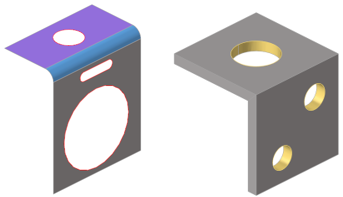
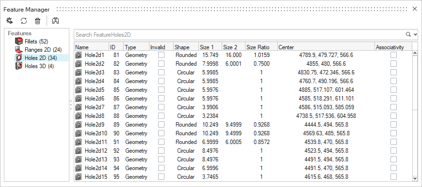
Features
The new Feature Manager allows detecting and managing geometric holes
(2D and 3D), fillets, flanges, and logos, as well as mesh holes and
flanges. After a feature is detected it will keep track of the geometry
or mesh defining it, and automatically update when modified by some
operations, like splitting edges or surfaces. Figure 12. Figure 13.
Enhancements
Split
Split with offset line now allows multiple offsets where you can specify
the number of offsets and width of the split.
Scale
Local system support added for parts, components, elements, and
nodes.
Mirror
Global plane entity support added for initial plane selection to mirror
selected entities.
Miscellaneous
Continuous improvement and bug fixes in lines, imprint, defeature, and
split geometry tools.
Meshing
New Features
Bulkhead
A new tool has been added under 2D Mesh in HyperWorks to create bulkheads that provide
localized performance benefits for multiple design attributes. For
example, NVH, Safety, and so forth. With minimal input, a bulkhead can
be created at a user-defined location along with their respective
parameters.
1D Mesh Property Update
A new tool has been added under 1D Mesh in HyperWorks called Section Property. It is exposed
for OptiStruct and Nastran solvers only. It enables you to update
properties with beamsections and materials as a result of a section cut
in a model. The source entities can either be surfaces, solids, or
elements (mix of shells and 3D solid elements).
1D elements are not yet supported as source for cut.
Multi materials are supported but not composite layered
shells.
Shells are inflated to represent actual shape.
Contact definition enables you to glue disconnected parts.
Shear Center and material weighted neutral axis are
calculated.
A generic beamsection is created along with an auto-calculated
material to account for correct stiffness terms.
Beam element is offset to account for element grid position with
respect to its shear center.
Limitation: section cut has a temp graphic in the tool but not
yet saved in a persistent way. Figure 14.
Box Trim
A new tool has been added to the Elements ribbon in HyperWorks.
With this new tool you have more control and flexibility, you
can add more than one graphical box, and those boxes can be
edited and moved interactively within the graphics area. Later,
those box faces (planes) are used for trimming of the complete
model, or the selected subset.
Graphical boxes can be quickly edited based on “Box Type” and
“Re-Oriented” with respect to global axis or with respect to
“best fit” method. This helps to quickly visualize and make
modifications before actual trimming.
Enhancements
BatchMesher/Rebuild
Support for rectangular/square, ellipse, slots, and mixed hole
shapes added for identification and various treatments (seeding,
washer creation, and removal).
Tria reduction and mesh flow improvements around free edges,
non-manifold edges, and washer regions.
Edit Elements Tool
Remap functionality added to Edit Elements tool. Remap a series
of nodes to a selected line list, the nodes become evenly
distributed across the line and you can select a set of nodes by
path and perform the Remap action.
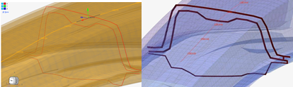
In the Move tool you can type the value in the micro dialogue to
move/optimize the node in the normal direction as shown
below. Figure 15.
In the case of hole/washer modify, the default preserve feature
is added and rebuild mesher is called for re-meshing.
The Split tool is enhanced to consider splitting underlying free
edges and 1d elements by default. In the case of fillets, middle
nodes would be projected to the parent surface.
Angle based correction method added under smooth function and
miscellaneous bug fixes done for Edit Elements
functionalities.
Thickness mapping tool is enhanced for Fixed interval method to
provide more control of thickness grouping.
Added an option to create mid-edge using discontinuous
guidelines in Midmesh Create Mid Edge tool.
Resolved Issues
Mesh flow issues corrected while splitting elements in midmesh using
node-to-node or node-to-shortest edge method.
Fixed bug related to Morph and Auto method in Replicate tool.
In the General 2D Mesh tool, corrected "Esc" behavior when using the Esc
key. Instead of directly closing the tool, now it takes you to "Create",
where you can select new surfaces/elements to redo meshing steps.
Reverse coloring allowed in HyperWorks
legend.
General bug fixes and robustness improvements.
Model Build
New Features
Instance Filter
Part Browser now has a predefined instance filter
that filters to show instances only. Based on selection, the filter
returns either all instances in the model, or siblings of the selected
instance. This predefined filter can be accessed from a list of queries
or manually applied. Figure 16.
Context Menus
Part Browser- and Subsystem Browser-specific context menu options are now
available by right-clicking in the graphics area when in idle.
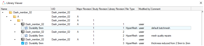
Representation Save Comments
When saving Parts or Subsystems, you can now add a user-defined
comment to assist in record keeping and track the changes made
between revisions.
The history of comments can be reviewed in Library Viewer. Figure 17.
Enhancements
Subsystem Browser Updates
The Subsystem Browser now follows paradigms set by the Model Browser and Include Browser and brings all the
functionalities of those views to the Subsystems.
This provides a clearer understanding of each Subsystems content
since all entities are shown in the browser including Node,
Element, and Connector counts.
Subfolders by Card Image for each entity type.
Invoke new view on double-click of folders for subsystem
specific views. Example: Figure 18.
Model Verification
New Features
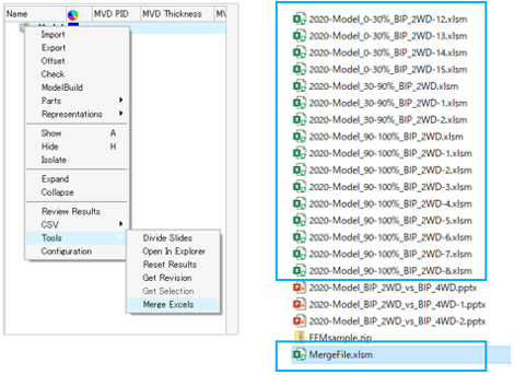
Merge Excels
This function lets you combine multiple comparison Excel reports into
one file.
Available in the context menu.
Keeps existing Excel reports but makes a new merged Excel
report. Figure 19.
Units
Comparison function that will convert all model units to mm and perform
comparisons.
Comparison tool will convert Length units to mm while importing
the CAD model.
Supported for Assembly and CAD inputs.
Meter vs MM and Meter vs Meter are converted to MM vs MM.
Auto converted without input required.
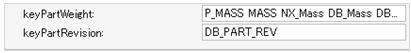
Part Revision
Supported in Comparison and Verification.
Revision information is read from Metadata and displayed in the
browser and Excel reports.
Revision numbers can be compared in an Excel report.
BOM comparison supports Part Revision attributes.
You can edit the Part Revision attribute name. Figure 20.
Enhancements
Quick Comparison extended to CAD vs CAD.
Comparison works similarly to CAD vs FE or FE vs FE.
Results are displayed in the graphics area with contours showing
matched/unmatched surfaces.
Performance is better than the default option.
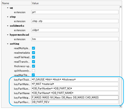
Read Metadata
User-defined metadata values can be read from Assembly or CAD
files.
PartNumber, PartName, Material, Thickness, Revision and other
attributes names can be modified from the Config file.
If the readMatThk option is ON, and if the PDM
attribute values are empty, the part attributes values from the
Metadata are given preference. Figure 21.
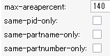
Comparison methods added
PartNumber, PartName, and PID based comparison.
While performing a comparison, parts that need to be compared
are auto searched. This option is used to force the search
criteria based on these 3 methods.
Performance is improved. Figure 22.
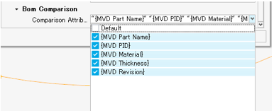
BOM Comparison
User-defined Part attributes are compared excluding the
topology.
Part attributes are compared excluding topology.
You can select any attributes to compare.
Reports generated in PowerPoint and Excel with H3d. Figure 23.
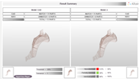
Report Enhancement
Comparison PowerPoint report enhanced to have detailed view on
the results.
Summary slides show results in detailed view with color
mapping.
Unmatched+Partial matched parts export option available for the
report generation.
Matched parts in transparency and unmatched parts in shading
mode available. Figure 24.
Miscellaneous Enhancements
Extend spotcomparison to support Opti format.
Thickness, Match%, Base thk, and Weight values are now shown in
2 decimals in all the reports.
Match function - Split Multi Solids, Multi Comps to Single
Part.
Assign dummy THK if thickness/property is missing in
Q-Comparison.
CDH spot file format is supported in Spotweld check.
Full path of the comparison result text file is editable from
the config file.
Known Issues
Excel Merge requires a good machine configuration.
Cumulative Match% displayed in the Comparison report needs
improvements.
Q Comparison function:
Needs a good machine configuration as 2 models will be read at
once.
Metadata is not read.
One variant supported.
Check runs on Interactive session.
Resolved Issues
Remove/disable Comparison and verification browser from Linux
hmdesktop.
Cadtofeapproach option with multiple CPUs not working when it is used for 1
vs 1 Part comparison.
Freepart check batch mode error is resolved.
Match Function, previous Part sets created are overwritten with current
run.
Check will be executed even if empty Part/Module is selected from the
Browser.
Morphing
New Features
Thickness-based offset
When mapping nodes to a target mesh in the Free and Proximity morphing
tools, you can now use automatic offset distances based on mesh
thicknesses at each node. After selecting the Target entities, you can
choose one of three different methods in the Targets microdialog to
define the offset. Figure 25.
Custom offset distance
Average thickness (t1 + t2)/2, plus custom offset value
Average thickness (t1 + t2)/2, multiplied by custom offset
value
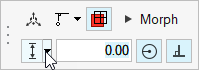
Enhancements
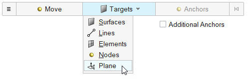
Map to plane
A new Plane entry has been added to the Targets selector inside the Free
and Proximity morphing tools. Use this selector to map nodes to a custom
infinite plane. Figure 26.
Resolved Issues
Delays when launching morphing tools on a fresh session have been resolved.
These were caused by a licensing-related service which has since been
improved.
An issue where using double-click to enter the reposition mode of the Move
manipulator was not working has been resolved. Now, either Shift or
double-click can be used to reposition the manipulator in any of the
morphing tools (as in the rest of the product).
Missing fading effect when entering the reposition mode of the Move
manipulator has been fixed.
An issue where it was not possible to create multiple design variables from
multiple selected shapes in the Shapes tool has been resolved.
Restore default options button not working in the Volume morph tool has been
fixed.
Resolved an issue where the split/combine microdialog would sometimes not
come back after performing undo operations.
Safety Tools
New Features
Seatbelt Tensioning
This new feature allows the simulation of a tensioning process on a
seatbelt segment directly in HyperMesh to
improve the quality of the belt path and remove slack between dummy and
belt. This feature is available in HyperWorks only.
Airbag Solutions
A new Airbag Solutions ribbon is introduced in HyperWorks. It contains a suite of workflows to
perform a complete airbag folding process: airbag patches stitching,
airbag folds and airbag fit into housing. Each step of the airbag
folding process uses Radioss, providing high
folding results accuracy.
Enhancements
THOR Dummy and IRTRACC manipulation
For THOR dummy, which contains IRTRACC kinematic systems, the dummy and
mechanism tools are automatically coupled to allow the motion of the
dummy by considering the mechanisms defined on the IRTRACCs.
Furthermore, the positions of the IRTRACC mechanisms are also considered
during the export of the dummy pre-simulation decks to simulate the
IRTRACC positioning.
Pedestrian Tool
The following enhancements are made in the Pedestrian tool:
Windshield Periphery Detection function for EuroNCAP will
automatically detect default green zone on windshield.
Ability to export only target csv file for selected impact
point.
GTR marking will automatically create Corner of Gauge
Block.
EuroNCAP/CNCAP/ EuroNCAP 2022-2023/CNCAP 2021 pedestrian marking
will create lower leg limit by bumper beam and plane touch
point.
Null beams creation for all marking lines through marking
options
Separate step size at marking option for Side Reference
Lines
Enhanced marking logic for Bonnet Rear Reference Line for active
hood condition.
Resolved Issues
Added correction while creating Radioss XREF in
the pre-simulation tools to generate it only on components defined in the
H3D file.
Resolved issue while creating Ball Joint (By Positions) in Mechanism.
5th attribute value “-3” on the first line of the MECHANISM data
written by Primer V17 is now supported.
Solver Attribute Mapping
New Features
Attribute Mapping
Automatic solver attribute mapping is supported for Components,
Properties and Materials when switching Solver Interfaces.
Mapped attributes include the Card Image and engineering
attributes such as a properties integration points and thickness
or a materials Young’s modulus and density.
Supported solvers include OptiStruct, RADIOSS, Abaqus, LS-DYNA,
NASTRAN, Permas and Samcef.
Solver-to-solver mappings are user configurable via the
configuration file located in the installation directory:
<ROOT\hwdesktop\hm\scripts\SolverConvertInterfaces\UnifiedConversion
>.
Solver Conversion
Enhancements
ADVC to Optistruct Conversion
Material Conversion:
ANISOTROPIC(SOLID) converted to MAT9
ANISOTRPIC(SHELL) converted to MAT2
ORTHOTROPIC converted to MAT9
ISOTROPIC converted to MAT1
ELASTIC-PLASTIC converted to MAT1/MATS1/MATT1/MATT4
GASKET converted to MGASK
Property Conversion:
SHELLTHK converted to PSHELL
MEMBRANETHK converted to PSHELL
AUTO_HM_SOLID converted to PSOLID
Sets Conversion:
ELEMENT_SET converted to SET_ELEM
NODE_SET converted to SET_GRID
SURFACE_SEG converted to SURF
Loads Conversion:
Load(force) converted to FORCE
Pressure converted to PLOADSF/PLOAD4
Load(moment) converted to FORCE
Forced Displacement converted to SPC
Contacts Conversion:
Contact type Small Sliding converted to Contact Pair, Small
sliding
Finite sliding converted to Contact Pair,CONSLI
Tying converted to TIE
Tying, RIGID converted to TIE,123456(DOF)
Friction, Static friction converted to PCONT,MU1
Friction, Kinetic friction converted to PCONT,MU2
Loadstep Conversion:
Static converted to Static/Nonlinear Quasistatic analysis
Eigen Value converted to Normal Modes
Abaqus to OptiStruct
*DLOAD converted to PLOADSF
Abaqus to Radioss
*COUPLING(DISTRIBUTED) TYPE=NODE converted to RBE3
*COUPLING (KINEMATIC) converted to RBE2
CAD and Solver Interfaces
Abaqus Interface
New Features
Mechanism Browser
Mechanism Browser support from crash profiles has been extended to the
Abaqus interface. The Mechanism Browser
allows for the creation of joints to transform and rotate components
with respect to each other using joint types like ball joint, revolute
joint, and so forth, to create desirable model configurations.
Compound Sets
A new set type called ‘compound’ is introduced to ensure preservation of
a node and/or element set defined across main file and multiple include
files upon import and export of those sets in the same order to main
input file and include files.
Analysis Procedure
A loadstep procedure to extract complex eigenvalues and corresponding
complex mode shapes has been introduced to the loadstep entity. Related
keyword is *COMPLEX FREQUENCY.
Enhancements
Grouping Materials in Entity Editor
The Entity Editor for materials has been enhanced to group materials
based on the physics.
New Keywords
*MASS FLOW RATE
*CONTACT INITIALIZATION DATA
*CONTACT INITIALIZATION ASSIGNMENT
*SUPERELASTIC
*DISCRETE SECTION
*ELECTRICAL CONDUCTIVITY
*MAGNETIC PERMEABILITY
*TRANSVERSE SHEAR
*COMPLEX FREQUENCY
*INTERGRATED OUTPUT
*INTERGRATED OUTPUT SECTION
*BEAM SECTION OFFSET (under *BEAM GENERAL SECTION)
Enhanced Keywords
*BEAM SECTION, TAPER
*NODE, NSET (Node set support at node definition)
*DLOAD with load label TRVEC
*CONNECTOR POTENTIAL under *CONNECTOR PLASTICITY and *CONNECTOR
FRICTION
New Element Configurations
Collapsed hex heat transfer elements (first and second order)
DC3D8 and DC3D20 for wedge elements.
PD3D – Particle element for explicit analysis.
AC3D5 and DC3D5 – New pyramid elements for acoustic and heat
transfer analysis respectively
Q3D4, Q3D6, Q3D8, Q3D10, Q3D20, and so forth – first and second
order tetrahedral, and hexahedral elements with wedge elements
(first order for wedges only) and their invariants for reduced
integration as well as hybrids (hyperplastic) for coupled
electrical-thermal-structural multiphysics analysis.
EMC2D3 and EMC2D4 – Triangular and quadrilateral elements for
electromagnetic analysis.
Resolved Issues
Resolved an issue with MODULI option that was applicable to anisotropic
hyperelasticity in conjunction with viscoelasticity.
An issue with leakage area equal to or greater than 1 that allows lower
value is resolved for *FLUID EXCHANGE ACTIVATION card.
Node set defined on *COUPLING as surface node definition in parts and
instances that failed on import has been fixed.
Surface defined for gasket elements had duplicate elements and this issue is
resolved to ensure duplicity is ignored.
Subroutine support for *FLUID BEHAVIOR is not relevant for explicit and it
is removed in explicit profile.
An issue of reading named entities with gaps for *SURFACE SMOOTHING card is
addressed.
Empty datacards for *ELASTIC with initial definition is not allowed for
Abaqus solver. This issue is resolved in
HyperWorks.
ADVC Interface
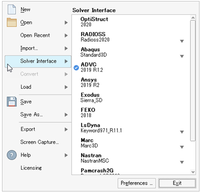
Highlights
The Solver Interface dialog displays options for performing model creation and for
setting up the ADVC Solver. Figure 27.
The following functions are available in the ADVC profile:
Assembly related
Geometry related
Mesh related
Model Browser
Entity Editor
EE Customization
Tool Tips
Create Cards
Menu Customization
Quick Search
HyperWorks Interface
Ribbon Customization
The supported version is 2019 R1.2
Solver Cards
Table 1. Element Cards
Element Type
Solver Card
2D Element
$ShellLinearTriangle
$ShellLinearQuadrangle
$ShellQuadraticTriangle
$ShellQuadraticQuadrangle
$MembraneLinearTriangle
$MembraneLinearQuadrangle
$MembraneQuadraticTriangle
$MembraneQuadraticQuadrangle
3D Element
$3DLinearTetrahedron
$3DQuadraticTetrahedron
$3DLinearPyramid
$3DLinearPentahedron
$3DLinearHexahedron
$3DIMLinearHexahedron
$3DRILinearHexahedron
$3DQuadraticPyramid
3DQuadraticPentahedron
3DQuadraticHexahedron
3D Gasket Element
$3DGasket6
$3DUniaxialGasket6
$3DGasket8
$3DUniaxialGasket8
Table 2. Material Cards
Material Type
Material Card
Isotropic
$YoungModulus
$YoungModulusInTable
$PoissonRatio
$PoissonRatioInTable
$Density
$DensityInTable
$ThermalConducitivity
$ThermalConducitivityInTable
$SpecificHeat
$SpecificHeatInTable
$ThermalExpansionCoefficient
$ThermalExpansionCoefficientInTable
$Density
$DensityInTable
$OrthotropicYoungModulus
$OrthotropicYoungModulusInTable
$OrthotropicPoissonRatio
$OrthotropicPoissonRatioInTable
$OrthotropicShearingModulus
$OrthotropicShearingModulusInTable
$OrthotropicThermalConducitivity
$OrthotropicThermalConducitivityInTable
$OrthotropicThermalExpansionCoefficient
$OrthotropicThermalExpansionCoefficientInTable
$SpecificHeat
$SpecificHeatInTable
$OrthotropicElasticity
Anisotropic
$Density
$DensityInTable
$OrthotropicYoungModulus
$OrthotropicYoungModulusInTable
$OrthotropicPoissonRatio
$OrthotropicPoissonRatioInTable
$OrthotropicShearingModulus
$OrthotropicShearingModulusInTable
$OrthotropicThermalConducitivity
$OrthotropicThermalConducitivityInTable
$OrthotropicThermalExpansionCoefficient
$OrthotropicThermalExpansionCoefficientInTable
$SpecificHeat
$SpecificHeatInTable
$AnisotropicElasticity
Gasket
$Density
$YoungModulus
$PoissonRatio
$ThermalExpansionCoefficient
$ThermalConducitivity
$SpecificHeat
$LoadingPath
$UnLoadingPath
$YieldPressure
$TensileModulus
$TransverseShearingModulus
$LongitudinalShearingModulus
$GasketInitialGap
$GasketThickness
ElasticPlastic/Elastic Attributes
$YoungModulus
$YoungModulusInTable
$PoissonRatio
$PoissonRatioInTable
$Density
$DensityInTable
$ThermalExpansionCoefficient
$ThermalExpansionCoefficientInTable
$SpecificHeat
$SpecificHeatInTable
$ThermalConductivity
$ThermalConductivityInTable
von Mises with Isotropic Hardening
$YieldStress
$YieldStressInTable
ElasticPlastic / von Mises with Isotropic Hardening
$MisesIsotropicHardeningCurve
ElasticPlastic / von Mises with Kinematic Hardening
$MisesKinematicHardeningCurve
ElasticPlastic / von Mises with Combined
Hardening
$MisesIsotropicHardeningCurve
$MisesKinematicHardeningParameter
Property Cards
$ShellThickness
$MembraneThickness
Sets Cards
$ElementSet
$NodeSet
$SurfaceSegment
$PretensionSectionNodeList
$PretensionSectionSurfaceList
$PretensionSectionElement
Control Cards
$CreatorInfo
$ModelInfo
Friction and Contact Cards
$Friction
$FrictionInTable
$KineticFriction
$KineticFrictionInTable
$MaxShearStress
$MaxShearStressInTable
$FrictionParameter
$ContactPair
$ContactParameter
LoadSteps and OutputBlocks
$Process
$ProcessSequence
$OutputParameter
$TimeHistory
$BarEvaluationPoint
AutoIncrementParameter
Temperature Analysis
$BarEvaluationPoint
Stress Analysis
$BarEvaluationPoint
$PretensionSectionNodeList
$PretensionSectionSurfaceList
$PretensionSectionElement
Enhancements
Changed effective_dof field in AUTO_HM_BEAM property to Check Box
selection.
QuickSearch extended to most of the keywords.
While selecting TimeHistory in Transient loads, curves are now
filtered.
Ability to create multi legged rigid elements from panel.
BCs and Loads creation widgets have the option to create/edit titles.
Resolved Issues
Heat Convection card with uniform option was not exported in expanded
form.
Field data was not exported for Friction card.
Reference position value under $HeatConvection card was not imported.
Load Browser not populated with required context menu items for creating
loads.
On reimporting solver deck, field data was missing for Maxshearstress
table.
Truncation of $ContactParameter and $TimeStep values are resolved.
Control Product Name and Product Version exports correctly.
Load Step review function shows loads in graphics.
Constraints can be reviewed through vector plot.
CAD Interface
Enhancements
Updated Version Support
NX 1953 (native reader)
Inspire 2021.1 (Import and export)
Resolved Issues
Fixed missing cad surface issues for Catia V5 Hybrid Body and
Catia composite parts.
Fixed scaling issues on part with JT assembly import as
BOM.
SI Unit conversion issue fixed when geometry imported as “single
part only” & “split component as layers”.
Fixed duplication of Parts in STEP file export for Part Assembly
instances.
Fixed crash issues with OCX file import.
Infinite plane is turned off for Catia import. It can be turned
on by setting the option "ImportInfinitePlane" to on in the
ctreader.ini file.
LS-DYNA Interface
New Features
Drive Mapping
On import of solver decks that contain includes, HyperWorks now allows mapping from one folder
path to another to import include files where the include path written
in the solver deck doesn’t match the location of the files. This
includes different paths due to different operating systems. Found in
Preferences > Drive Mapping, or in the Solver Deck import options, you
can define the source path where the files reside, and the target path
as written in the solver deck, and use this to successfully import files
without the need to edit the include paths in a text editor.
Include Organization
The Organize context menu option is now available for all entities. The
organization of entities into an include file has been improved to
automatically consider all references linked to the selected
entities.
New Reference Geometry Entities
The Reference Geometry entity provides a better support of the airbag
reference geometry and foam reference geometry keywords. A dedicated
graphical representation allows for the visualization of the airbag
patches. The interactive modification of the nodes defining the
*AIRBAG_SHELL_REFERENCE_GEOMETRY is also possible directly on the
graphic.
New Load Entities
Some load and boundary keywords are migrated from the Load Collector
entity to the dedicated Loads entity.
Enhancements
Creation of Curves
Efficiency improvement for creating/editing curves from any keyword
entity editor by directly exposing the curve editor and accessing the
curve X;Y data.
Mechanism in Assembly Ribbon
HyperWorks-specific. The Mechanism tool is
now directly accessible from the Assembly ribbon, like any other solver
interface supporting this tool.
Export issue in the third line of *DATABASE_CROSSSECTION_PLANE of type
circle.
Transformations not applied on the correct include, when the include defined
in *INCLUDE_TRANSFORM is not referenced in the model.
Export issue with field HISn of *MAT_ADD_GENERALIZED_DAMAGE.
Export issue in *DATABASE_OPTION when binary format is not specified.
Export issue in D2R line of *DEFORMABLE_TO_RIGID_AUTOMATIC.
Entity Editor limit is extended up to 100 for NVENT
in *AIRBAG_PARTICLE.
IDROFF offset value in *INCLUDE_TRANSFORM will not apply on control cards
anymore.
Addition of node and direction selection options to Vector entity
creation.
Nastran Interface
New Features
Contact Browser Enhancements Nastran (NX)
Contact browser supported in Nastran (NX) interface similar to Nastran (MSC) interface.
Auto contact tool support extended to Nastran (NX).
BCTSET, BGSET contact types are supported through contact
browser for auto creation and manual creation.
BSURF card migrated to set entity.
BSURFS card migrated to set segment entity.
ID Pool for Elements
Connector elements (RBE2,RBE3,RJOINT,RBE1, GENEL,etc),
Aeroelasticity panels, and structural elements can share same ID
space in Nastran.
To handle Nastran behavior, the interface now supports ID pool
for structural and connector elements.
Duplicate ID's are supported for elements, properties,
aeroelasticity panel, and HyperMesh
entities in the Nastran (NX)
interface.
A new solver option added in import browser, “renumber the ids
to match solver ids,” for elements with shared id space are
synced with solver ids during import process.
Mechanism Browser
Support of Mechanism Browser is extended to Nastran interfaces.
Create and articulate a kinematic mechanism based on FE mesh
using available joint types in the Mechanism Browser.
In HyperWorks, the browser is
invoked through Mechanism tool on the Assembly ribbon.
LoadStep Inputs Entity
New entity to migrate Nastran bulk
cards from loadcolletor to loadstep inputs entity with
engineering configuration.
Some of the bulk cards, for example EIGRL, EIGRA, EIGC, NLPARM,
and so forth, are migrated to loadstep inputs entity.
Visualization Support for LOADADD
LOADADD card is mapped to the loadcollector entity which is
defined with a scale factor for each load in the list.
Visualization of LOADADD is possible as a vector plot or contour
including the scale factors from the Solver Browser.
Load referenced in LOADADD must be new load management
entity.
Enhancements
General Enhancements
Enable Large or Standard format export setting for individual
includes.
TABLED1/TABLES1/TABLEM1 cards with large precision are exported
in comma-separated format by default.
Resolved Issues
HyperWorks was missing “export DMIG in large
format” option.
NLPCI import issue with undefined type in NLPARM card.
CTRIAR missed component organization on export.
OptiStruct Interface
New Features
ID Pool for Elements
Connector elements (RBE2,RBE3,RJOINT,RBE1, GENEL,etc),
Aeroelasticity panels, and structural elements can share same ID
space in OptiStruct.
To handle OptiStruct behavior, the
interface now supports ID pool for structural and connector
elements.
Duplicate ID's are supported for elements, properties, and
aeroelasticity panel HyperMesh
entities in the OptiStruct
interface.
A new solver option added in import browser, “renumber the ids
to match solver ids,” for elements with shared id space are
synced with solver ids during the import process.
Mechanism Browser
Support of Mechanism Browser is extended to OptiStruct interfaces.
Create and articulate a kinematic mechanism based on FE mesh
using available joint types in the Mechanism Browser.
In HyperWorks, the browser is invoked through the Mechanism tool
in the Assembly ribbon.
Loadstep Inputs Entity
New entity to migrate OptiStruct
bulk cards from loadcolletor to loadstep inputs entity with
engineering configuration.
Some of the bulk cards, for example EIGRL, EIGRA, EIGC, NLPARM,
NLOUT, NLADAPT, and so forth, are migrated to the loadstep
inputs entity.
Visualization Support for LOADADD
LOADADD card is mapped to loadcollector entity which is defined
with scale factor for each load in the list.
Visualization of LOADADD is possible as vector plot or contour
including the scale factors from the Solver Browser.
Load referenced in LOADADD must be new load management
entity.
Nonlinear Analysis Enhancements
NLPRINT bulk card supported in loadstep inputs entity to control
printing of certain information to the
_nl.out file for nonlinear
analysis.
NLENRG bulk card supported in loadstep inputs entity to print
energy variables for implicit nonlinear static and implicit
nonlinear transient analyses.
BASELIN bulk card supported in loadstep inputs entity to correct
the acceleration record to avoid displacement shift.
Optimization Enhancements
Method of Moving Asymptotes (MMA) option added to OPTMETH
parameter in DOPTPRM card.
DTPL card enhanced with LEVELSET continuation line to support
level set method in topology.
Thermal Analysis Enhancements
IC subcase selection in transient heat transfer subcase allows
reference to steady state or transient thermal subcases.
Output Request Enhancements
TOTALFORCE option to request total force (a summation of
single-point force and applied load).
PSDFC option to output PSD, RMS and RMS (cumulated) results from
random response analysis.
RESULTANT option to enable output of resultant forces and
moments for internally generated sections.
Enhancements
General Enhancements
Enable Large or Standard format export setting for individual
includes.
TABLED1/TABLES1/TABLEM1 cards with large precision are exported
in comma-separated format by default.
DT and N fields in TSTEP export as blank for nonlinear transient
analysis.
PARAM, LGDISP,-1 removed from OptiStruct interface.
Resolved Issues
HyperWorks was missing “export DMIG in large
format” option.
Export issues with MCOHED card in comma-separated format.
NLPCI import issue with undefined type in NLPARM card.
SUBID field in IMPERF card does not user defined subcase ID.
SORIENT field export issue with contact card.
DREPORT can't be activated for a response that is referenced in a
constraint.
MATHE (OGDEN) bulk card exports undefined fields as zero.
Remove obsolete option LOADTEMP from SYSSETTING card.
New modular keywords MMAT, MPART (ATYPE = SHELL, SOLID), LOOKU, NUMPAR,
SECURE (ENCRYTYP = MMAT, MPART) are supported. Added new failure entity
to create Damage and Failure Parameters of MMAT. Mapped Look-Up Table
Card (LOOKU) to curve entity with ARGUMENT and FUNCTION as
attributes.
Transformation sequence
Added new keyword TRSSEQ and mapped to Position/Transformation entity.
Transformation Sequence cards allow you to specify a sequential order in
which the transformations (TRSFM) will be performed. Model Checker will
give a warning if TRSSEQ is empty or if there are no references of TRSFM
definitions.
Reference geometry
The Reference Geometry entity provides better support of the airbag
reference geometry keyword METRIC. A dedicated graphical representation
allows the visualization of the airbag patches. The interactive
modification of the nodes defining the METRIC is also possible directly
on the graphic.
ID parameterization
Added support of keyword ID parameterization of PAM-CRASH keywords SENSOR, DELEM, FUNCSW, FUNCT,
SECURE_FUNCT, FRAME, RUPMO, CDATA, CHEM, CNTPTY, DMPEW, FRICT, LAYER,
NLAVE, OPTLIS.
Undefined GROUP (Sets)
Support of undefined GROUP (Set) entity, keyword has Defined checkbox
toggled off and is automatically not exported. The “GROUP /" keyword
referenced through GRP, OGRP, GRP>NOD, DELGRP, DELOGRP, DELGRP>NOD
selection is maintained even if the definition does not exist. Undefined
sets are merged by name as opposed to ID. Added info check into model
checker to report the number of defined and undefined Set GROUP
keywords.
Enhancements
PART (ID of NUMAPR can be referred to under IDNUMPAR), MATER (ID of LOOKU
can be referred to Material Type 1, 52, 117, 304, 307), FRICT (ID of LOOKU
can be referred to type IFROPT = 13), PFSURF (QUALIFIER=LOOKUP and
VALUE=ID), METRIC, GROUP.
Penetration check accounts for minimum thickness instead of maximum in
common edge nodes.
Resolved Issues
SECFO keyword entity selection field labels are renamed to Main and
Secondary entity IDs.
Prime control card PROFILE_DMP is printed before other data to avoid solver
errors.
IDNUMPAR of PART card is an entity selector that refers to the NUMPAR
keyword.
Look-Up ID of MATER (Type 1, 52, 117, 304, 307), FRICT (IFROPT = 13) and
PFSURF cards is an entity selector that refers to the LOOKU keyword.
Added ID pool support for new style entities TRSFM, TRSSEQ, PICIMP, PICEXP
to avoid renumbering. Keywords list in ID Manager individually rather in
single Position entity.
Radioss Interface
New Features
Exported Decks Formatting
For the Radioss profile 2021, the format of
the exported decks has been fully redefined, with the export of all
solver keywords field names and the re-ordering of the keyword blocks in
a more comprehensive and consistent way.
Include Organization
The Organize context menu option is now available for all entities.
Furthermore, the organization of entities into an include file has been
improved to automatically consider all references linked to the selected
entities. This feature is also available performing drag and drop of an
entity into an include file.
New Reference Geometry Entities
The Reference Geometry entity is introduced to provide a better support
of the airbag reference geometry and foam reference geometry keywords. A
dedicated graphical representation is used which allows the
visualization of the airbag patches. The interactive modification of the
nodes defining the /EREF is also possible directly on the graphic.
The support of /RBE3 has been updated to remove all existing limitations
and get a correct description of the element in the Entity Editor.
Creation of Curves
Efficiency improvement for creating/editing curves from any keyword
entity editor by directly exposing the curve editor for a direct access
to the (X;Y) data.
Mechanism in Assembly Ribbon
The Mechanism tool is now directly accessible into the Assembly ribbon,
like in any other solver interfaces supporting this tool.
Model Checker Enhancements
New check for “Material and property are not compatible."
New check for “Material and element type are not
compatible."
New check for “Property and element type are not
compatible."
New check for “Multiple RBODY sharing common nodes” and
corresponding automatic correction to automatically merge the
RBODYs.
New check for “Empty Components” and “Empty Dampings” and
corresponding automatic deletion of failed entities.
Automatic correction added for the check “RBODY main node on
element."
Automatic correction added for the check “Small rigid body with
non-spherical inertia."
Correction of check “LAW2, 4, 15, 27, C and Eps0 defined but
Fsmooth and Fcut blank."
Correction of checks “Main set not defined” and “Secondary set
not defined” for contacts TYPE19, TYPE24 and TYPE25.
Enhancements
Reader
Reader enhancement to support 3 nodes and 4 nodes spring elements when
importing Radioss input deck.