The Plane and Vector selector is used in many panels, the
Entity Editor or dialogs to define a plane or a vector
(direction) to perform a certain function.
For example, the Translate panel requires that you define the direction of translation,
while the Reflect panel requires a plane for the creation of the mirror images of the
entities selected.
A plane can be defined with a vector (the plane is normal to the vector specified), just
as a vector can be defined with a plane (the vector is normal to the plane specified).
Either can be defined via the Plane and Vector selector. Figure 1. Plane and Vector Selector
Note: Some selectors may resemble the Plane and Vector selector, but serve a
different purpose. Figure 2. Selector in Position and Linear Solid Panels. Selector resembles the Plane and Vector selector, but is used to map
entities from one location to another.
The Plane and Vector selector consists of several options. Not every item appears at all
times; only the items necessary for the current function will display.
(Switch)
Select the method for defining the plane or vector.
x-axis, y-axis, and z-axis
Define the first, second or third axis respectively of a
coordinate system in your model. This coordinate system may be
the global coordinate system, or a local system when one can be
explicitly specified. Local systems may be rectangular,
cylindrical or spherical.
vector
Specify a vector entity (created in the Vectors panel). This
includes vectors defining coordinate systems, and loads as
well.
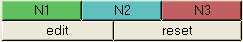
N1, N2, N3
Define a vector (N1,N2), or plane (N1,N2,N3). When defining a
plane, the resulting vector is normal to this plane following
the right hand rule, and passes through either N1 or the base
node (if one is specified).
screen normal
Define a vector that is normal to the screen. For planes, as the
vector defines the plane normal, the plane is within the
screen.
screen parallel
Define a vector that is within the screen. For planes, as the
vector defines the plane normal, the plane is perpendicular to
the screen.
Node Buttons
When a node button is active (outlined with a blue border), you can select a
node in the modeling window to automatically define
it's coordinates. You can also click a node button to manually enter a
node's coordinates. Once a node is selected, the next node button will
automatically become active.
The B (base node) button defines the point in space where the vector or
plane is located. For example, selecting a plane of projection using the
x-axis does not define the location of the plane entirely. A base node
provides the extra information. When using the N1, N2, N3 option, N1 is used
as a default base node if no other base node is specified.

 (Switch)
 (Reset)