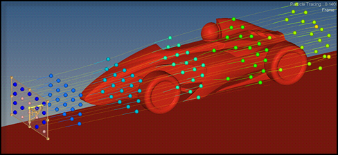
Particle tracking can be used to animate streamlines of steady state CFD results.
The tracers are injected into the fluid domain at the beginning of the streamlines and
travel along the streamlines. Different tracer designs, coloring options and injection modes
are available. Figure 1.
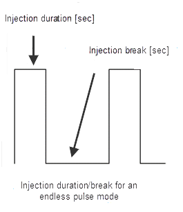
Pulse
Two options are available
Single
A new set of tracers is injected after all previously injected tracers have
reached the end of the streamlines.
Endless
Tracers are continuously injected with a user defined injection break.
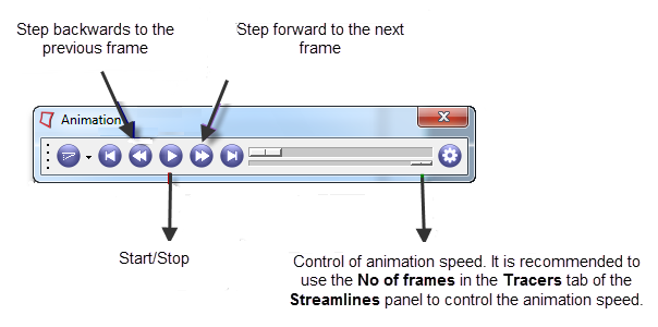
No of frames
Number of frames used for the animation. A higher value results in a slower
animation, a lower value will increase the animation speed.
Injection duration
This parameter is only editable if the body of the tracers is defined as Segment.
The value controls the length of the injected line segments. Comparing the situation
with an ink injector, the injection duration describes for how long the ink is
injected into the fluid.
Injection break:
This parameter is only editable if the Pulse option is set to Endless. The value
specifies the time difference between two injections of tracer sets. Comparing the
situation with an ink injector, the injection break describes the time interval in
which no ink is injected.
Figure 2.
A tracer consists of a head and a body. Both representations can be defined
individually.
Head
Defines the head of the tracer. The options are Sphere or
None.
Body
Defines the body of the tracers. The options are Segment or
None.
Create
Creates the tracers and starts the animation.
Color by
Three options are available:
Seed
Each seed node is associated with a particular color. The number of used
colors can be defined by No of colors in the Streamlines tab. The tracers
injected by a seed node are colored according to the node’s associated
color.
Rake
All tracers emitted from one rake are colored with the same color. The color
of the rake can be controlled via the Session Browser.
Injection time
All tracers injected at one point in time are colored with the same color. The
number of used colors can be defined by No of colors in the Streamlines tab.
Size
This parameter controls the size of the spheres. If only Segments are activated the
thickness of the segments is controlled with this parameter.
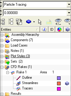
Defining tracers also generates entries in the Session browser in the section for CFD
Rakes. By clicking the tracers symbol, the tracers of a particular rake can be activated or
deactivated. The color of the tracers can be changed by clicking the color box behind the
tracer entry and then selecting a color. The color selection has only an effect if Color by
rake is selected in the Tracers tab. Figure 3.
Animation Control
The animation can be controlled via the Animation toolbar. Figure 4.
The coordinates for the reference points defining a line rake or a plane rake can be
entered via the Reference point dialog. To open the dialog click in the Streamlines panel.
 in the Streamlines panel.