Use the Generate 2D BL Mesh utility to generate 2D meshes with or without boundary
layers on planar or non-planar sections defined by sets/groups of edges defining closed
loops.
A region is considered closed if it is entirely bounded by edge elements (edge elements
should be of type PLOTEL). Element configurations generated by this utility are linear
quadrilateral (quad4) and triangular (tria3).
To access this utility, click Mesh > Surface Mesh 2D > 2D Mesh with BL.
The following options allow you to create a 2D mesh with or without boundary layers from
groups of edges defining closed and non-intersecting loops.
2D Smooth BL Tab
Region
Select the surfaces or the elements that make up the region.
Default selection
Specify the default boundary type.
With boundary layer
Select the desired line.
Number of layers
Specifies the number of boundary layers to be generated from all the elements in
components with type Wall. No boundary layers will be generated from components with
type Wall if the value of the number of boundary layers is set to zero.
First layer thickness
Desired thickness for the first layer of elements.
BL growth rate
Boundary layer thickness growth rate from layer to layer.
Element size
Enter the desired element size value.
Element type
Select the type of elements to generate: quads, trias, mixed or R-trias.
Elements to region component
Places newly generated elements into the region's component.
BL reduction
Reduces the boundary layer thickness.
Manual
Opens the Distributed BL Thickness Ratio dialog.
Auto
Opens the Generate BL Thickness dialog.
When Surfaces is selected as the region in the 2D Boundary Layer
Mesh dialog, the Generate BL Thickness and Contour of BL Thickness ratio
buttons are grayed out. You can still enter values in the two text fields. They are used
for a dynamic BL reduction, meaning the BL proximity checks are performed during
generation and the height is reduced accordingly.
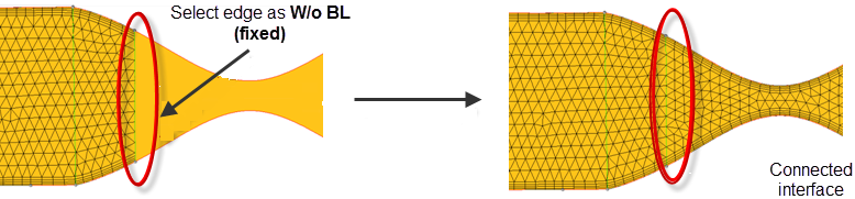
Example for W/o Boundary Layer (fixed)
If a 2D region is split into several parts and meshed sequentially, you have to make sure
to have a connected mesh at the interface. Selecting W/o BL (fixed) ensures a connected
mesh. Figure 1.
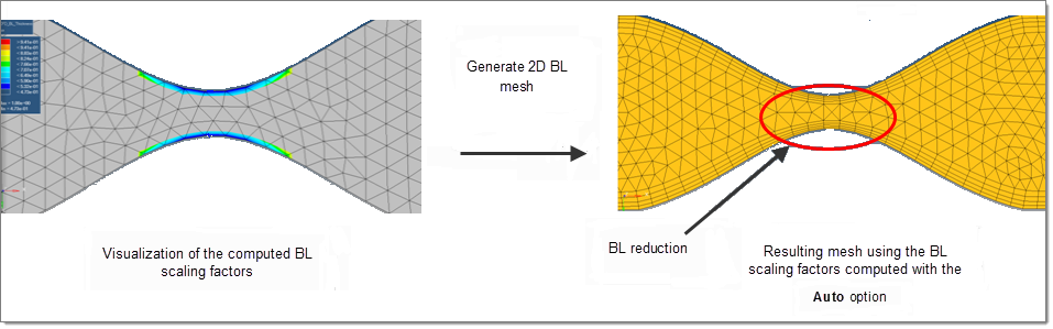
Example for BL Thickness Reduction
In narrow regions the BL thickness has to be adjusted to avoid mesh intersection. Two
options are available: Auto and Manual.
Auto
If the region to be meshed is specified by Elements Engineering Solutions will perform a proximity check based on the
boundary nodes of the With BL boundaries and compute BL thickness scaling factors to
avoid BL intersections.
If the region to be meshed is specified by Surface Engineering Solutions will perform two steps. In the first step,
a mesh is generated in the background using the user defined Element size and the
boundary nodes are used to calculate the BL thickness scaling factors. In the second
step the BL and the final core mesh is generated using the before computed scaling
factors for the BL thickness.
Manual
The BL thickness scaling factors can be manually assigned to the boundary
nodes.
Contour of BL Thickness ratio: This option can be used to generate a contour plot of
the existing BL scaling factor. Clicking Manual in the 2D Boundary Layer
Mesh dialog opens the Distributed BL Thickness Ratio
dialog, where the Contour of BL Thickness Ratio option is available. Similarly,
clicking Auto opens the Generate BL Thickness dialog, which also
has the Contour of BL Thickness Ratio option.
Below is an example for auto BL thickness reduction. Figure 2.
2D Native BL (planar) Tab
1st Layer Thickness
Desired thickness for the first layer of elements.
Growth Rate
Boundary layer thickness growth rate from layer to layer.
Bound Type
When Bound Type is set to Wall, boundary layers are generated along the component
edges. No boundary layers are generated when Bound Type is set to Farfield, Inlet,
Outlet and Symmetry. Note that edge elements in collectors having Bound Type defined as
Farfield, Inlet, Outlet and Symmetry will be used to define the geometry, but they will
not dictate element size/density.
Set defaults
Used to assign the default values for 1st Layer Thickness, Growth Rate and Bound
Type.
Add collector
Used to select collectors with edge elements that define the boundaries of the domain.
Selected collectors are populated in the Components Table with the default values set
for 1st Layer Thickness, Growth Rate and Bound Type.
Component Selection
Use the radio buttons to quickly select all or no components, or reverse the current
selection.
Remove
Used to remove the selected collectors from the Components list.
Number of boundary layers
Enter the number of boundary layers to create.
Allow boundary node insertion
Option to refine the boundary edges to generate boundary layer type meshes with the
maximum desired element aspect ratio.
Allow boundary node movement
Option to move boundary nodes to generate boundary layer type meshes with the maximum
desired element aspect ratio.
Retain node seeding on edge w/o BL
If this option is checked, the node seeding on the edge without BL is maintained as
much as possible. The nodes on the non-BL boundary which are located inside the BL will
not be maintained, only the nodes which are located outside of the BL will be
maintained.
Max perimeter element aspect ratio
Used to refine the boundary edges (inserting nodes and/or moving nodes) to meet the
specified aspect ratio.
Generate 2DBL mesh
Generate the mesh with the selected edges and associated settings.