Creating the Model

Create the model in CADFEKO. Define any ports and sources required for the model. Specify the operating frequency or frequency range for the model.

  1. Delete the edge ports.
    Note: The S-parameter configuration reverts to a standard configuration
  2. Expand shielded_filter and separately delete Feed1 and Feed2.
  3. Set the region properties of the two regions back to the default, namely MoM/MLFMM with surface equivalence principle (SEP) - default.
  4. Delete all horizontally orientated faces except that of the top of the box, the microstrip line and stub.
  5. Add a planar multilayer substrate (infinite plane) with a conducting layer at the bottom.
    1. Select Plane / ground.
      • Click Planar multilayer substrate.
      • Thickness (Layer 1): substrate_height
      • Medium (Layer 1): substrate
      • Ground plane (Layer 1): PEC
      • Z value at the top of layer 1: substrate_height
  6. Add microstrip ports to the edges of the feedline (see Figure 1 and Figure 2).


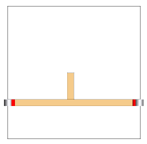
    Figure 1. Microstrip ports were added to the edges of the feedline. Note that the infinite plane is hidden and a cutplane was added to show the port locations.


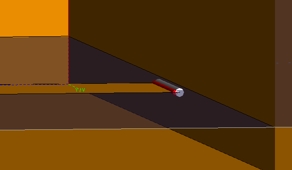
    Figure 2. Zoomed in 3D view of one of the microstrip ports.
    Tip: The microstrip port can be used with infinite substrates. The port construction is simpler than the edge port since the port connects to a single edge only. If the phase of the results are required, set the polarisation of the port accordingly. The positive terminal is indicated by the red cylinder in the 3D view.
  7. Set a local mesh size on the microstrip lines (faces) of strip_width/2.