Insight
When the "Insight" option is selected, the following panel is shown:
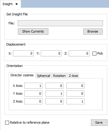
Figure 1. Insight panel
This panel allows the user to add a new Insight antenna. An insight antenna is a type of antenna that is defined by an Insight file (a file with a .ins extension). This file defines a geometry made from points, where each point is assigned a current density.
The user can import a INS file by pressing the "Browse" button and selecting the file in their hard drive. Before adding the Insight antenna to the simulation, the user needs to specify the following parameters:
- Displacement: This parameter is a vector that specifies the translation applied to the points of the insight file when added to the simulation.
- Orientation: This parameter allows the rotation of the points of the Insight file. There are several ways the user can specify this rotation by giving each of the axis directions of the transformation, by specifying spherical rotation angles, by specifying rotation angles on each axis or by specifying the Z axis and a rotation angle.
If the "Relative to reference plane" check box is checked, the displacement and rotation will be relative to the current reference plane coordinate system.
The user can also choose to view a 3D diagram of the current densities of the imported Insight file by pressing the "Show Currents" button:
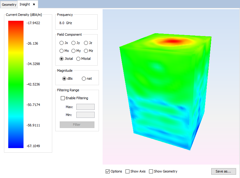
Figure 2. Insight currents panel
In this panel, the user can select the component of the current density that is displayed in the diagram, as well as choose the magnitude and filter the displayed values to be between a given range. The check boxes below the diagram allow the user to hide/show the left panel, show/hide the axes and show/hide the wireframe of the Insight antenna geometry. The user can also save the diagram as a PNG image file by pressing the "Save as..." button.
When the user has finished setting up the parameters of the Insight antenna, they need to press the "Save" button in order to actually add the antenna to the simulation.