Apply an edge port to an edge defining the boundary between two sets of
faces.
-
On the Source/Load tab, in the
Ports group, click the
 Edge port icon.
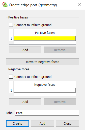
Figure 1. The Create edge port (geometry) dialog.
When an infinite ground plane is present in the model, any edges that lie
in the plane can be excited with respect to that ground plane.
-
Connect a side of the port to the infinite ground:
- To connect the positive side of the port, under Positive
faces, click the Connect to infinite
ground check box.
- To connect the negative side of the port, under Negative
faces, click the Connect to infinite
ground check box.
Specify the positive faces of the edge port.
-
In the Positive faces table, use point entry to specify
the positive faces using one of the following workflows:
- In the 3D view, click on the relevant face.
- In the details tree, click on the relevant
face.
Specify the negative faces of the edge port.
-
In the Negative faces table, use point entry to specify
the negative faces using one of the following workflows:
- In the 3D view, click on the relevant face.
- In the details tree, click on the relevant
face.
-
Click the Create button to create the edge port
and close the dialog.
-
[Optional] To switch a face between the lists, select one of the following
workflows:
- Double-click the face entry.
- Click Move to ... faces.
-
In the Label field, add a unique label for the edge
port.
-
Click the Create button to create the edge port
and close the dialog.