Create a Projector Light
Projector light functions almost identically to spot light, but it can also be used to display images. It simulates a LCD projector and emits light in the shape of a square pyramid to display images on surfaces. Projector lights are useful for quickly achieving visual effects that would otherwise require laborious modeling (e.g., instead of individually modeling window bars, use a black-and-white striped image to simulate filtered light).
 Figure 1. Example of a Projector Light with an ISO of 100
You may want to decrease the intensity of the global environment if you plan to add lights to your scene.
Light Parameters
- Power Unit
- The default is Unitless, which measures intensity using arbitrary units
that do not directly relate to the power output of a lamp or any other
such physical measurement.
To simulate a real world commercial light bulb, select a specific unit of power (Lumens, Candelas, etc.).
- Efficacy
- (Only applies to Watts and Watts/sr.)
Define the luminosity of the light source in lm/Watt.
Tip: Specific light sources have specific values (e.g., a 100-Watt tungsten incandescent lamp has an efficacy of 12-18 lm/W, while a good LED light might have an efficacy of about 100 lm/W). You can find a table of data at http://en.wikipedia.org/wiki/Luminous_efficacy. - Attenuation
- Define the loss of light intensity based on the light-object distance.
- Color
- Define the color of the light by choosing a plain color from the color palette. It is recommended to use subtle, light colors for better results.
- Caustics Photons
- Caustics is a technique that mimics real light by calculating photons
that start at a light source. If Caustic Photons is enabled, these
photons are reflected, refracted, and bounce off the surface of a
mirror, for example. Some lights in your scene may not produce caustics;
for these, disable Caustics Photons to save rendering time.Note: This feature is not currently available in GPU+CPU mode.
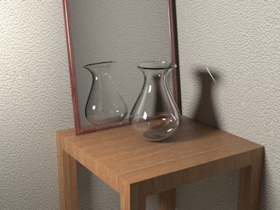
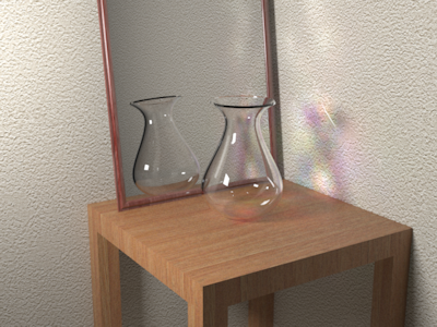
 Figure 2. Caustics Off
 Figure 3. Caustics On
 - Shadow
- By default, all objects cast and receive shadows when illuminated by a
light source; however, there may be situations where this is
undesirable. For instance, certain objects cannot produce a visible
shadow due to the viewing position. Excluding these objects from shadow
calculations can result in improved rendering performance, both in terms
of increased speed and reduced memory usage.Note: This option only applies to Raytracing; it does not affect the Interactive Rendering or Full (Progressive) rendering engines.
- Reflection Based Positioning
-
- Select a light.
- Do one of the following:
- To place the light perpendicular to the point where you will click, for the Placement Method, select Illumination.
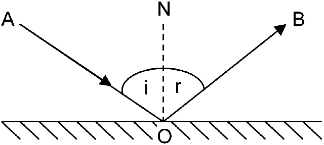
- To place the light in the opposite direction, for the Placement Method, select Reflection. In the figure below, if A is the camera and O the point where you click, the light will be placed at point B. This feature allows the camera to receive the maximum amount of reflection.
- To place the light on a surface, click the Place on Surface button, and then click the surface.
- Define OB:
- To make OB equal to AO, for the Placement Distance, select Same as Camera to Point.
- To define a custom OB, for the Placement Distance, select Custom, and then type a Distance Value.
