Modeling MIMO in Network Planning
For considering MIMO antennas in the WinProp radio network planning project, first the MIMO scheme has to be selected on the Air Interface tab. Depending on the selected MIMO scheme, a number of separate MIMO data streams is considered (either MIMO 2x2 with two parallel streams or MIMO 4x4 with four parallel streams).
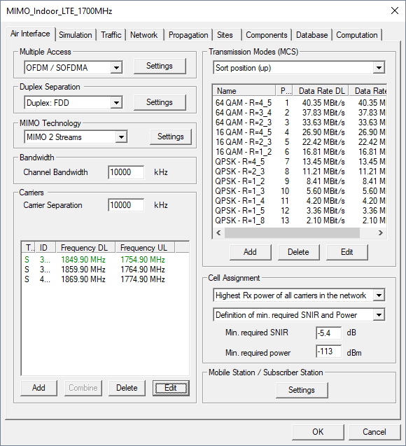
Figure 1. Air Interface definition including MIMO technology.
When you click the Settings button, further properties of the MIMO antenna system can be specified.
Signaling Overhead
When transmitting multiple data streams in parallel due to spatial multiplexing, there is an additional signaling overhead required which reduces the effective achievable data rate. The defined value is considered once for MIMO 2x2 and twice for MIMO 4x4.

Figure 2. MIMO Settings regarding beam forming.
Beam forming
Beam forming at the transmitter can be achieved by spatial processing. In this case the same signal is emitted from each of the transmit antennas with appropriate phase weighting such that the signal power is maximized at the receiver input.
The benefits of beam forming are to increase the received signal gain, by making signals emitted from different antennas add up constructively, and to reduce the multipath fading effect. Spatial multiplexing can also be combined with beam forming when the channel is known at the transmitter.
In the absence of scattering, beam forming results in a well defined directional pattern, thus increasing the antenna gain for the desired signal and reducing the antenna gain for the interfering signal. Consequently the antenna gains for the serving and interfering signals can be defined in the MIMO settings if beam forming is utilized. These values shall be kept to 0 dB if no beam forming is applied.
Interference between MIMO streams
Spatial multiplexing by using MIMO antennas allows to increase the throughput depending on the signal-to-noise-and-interference ratio (SNIR). The SNIR is also influenced by the interference between the different MIMO streams.
- No interference (ideal separation of different streams)
- If different polarizations are used (for example, vertical polarization for MIMO stream 1 and horizontal polarization for MIMO stream 2) the streams are well separated, especially in LOS areas. Thus a simple assumption consists in neglecting the interference between the different MIMO streams.
- Relative contribution to interference due to non-ideal separation of streams
- In this case an overall ratio for the interference between the different streams is specified. For example, 20 dB which means that for a MIMO 2x2 system the received power for MIMO stream 1 will increase the interference level for MIMO stream 2 (received power minus 20 dB) and vice versa. This option considers a constant relative interference impact over the whole simulation area (considering the individual received power values for each stream at each location).
- Location dependent determination of interference due to non-ideal separation of streams
- This option considers the individual receiver location and the properties of the radio link (LOS/NLOS) for the interference impact. In order to ensure high accuracy the user shall define if different polarizations are used for the individual MIMO streams (for example vertical polarization for MIMO stream 1 and horizontal polarization for MIMO stream 2), which reduces the interference, especially in LOS conditions.
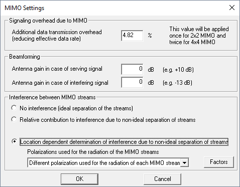
Figure 3. MIMO Settings regarding the interference between different MIMO streams.
Antenna Definition
Generally the antennas belonging to MIMO systems are defined in the same way than conventional antennas, location, carrier frequency, and transmit power of the antennas are defined as usual. For each MIMO antenna element a separate antenna has to be defined in ProMan.
The Signal Group has to be set to the same ID for all antennas belonging to a MIMO system. Furthermore the transmitted MIMO stream has to be selected.
For conventional antennas, the Signal Group ID is set to individual (no MIMO stream can be selected). Generally all antennas belonging to a MIMO system must have the same carrier. Depending on the assigned Signal Group ID and the assigned MIMO stream the signals from different antennas are combined constructively or interfere each other.
| Antenna Type | Signal Group | MIMO Stream |
|---|---|---|
| Conventional antenna | Individual | Not available |
| Antenna belonging to DAS | A / B / C / … | No MIMO |
| Antenna belonging to MIMO | A / B / C / … | MIMO stream 1 / stream 2 |
To specify the MIMO Stream, click and click the Sites tab. Select a site and click Edit. Select an antenna, click Edit and click Edit Carrier.
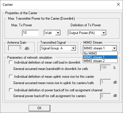
Figure 4. The Carrier dialog.
The Signal Group and MIMO stream selection can be found in the carrier settings of a transmitter.
All antennas belonging to one MIMO system must have the same Signal Group ID. If only one MIMO system is available in your project it is recommended to use Signal Group A for all antennas which are part of the MIMO system.