Functions of the Control Panel
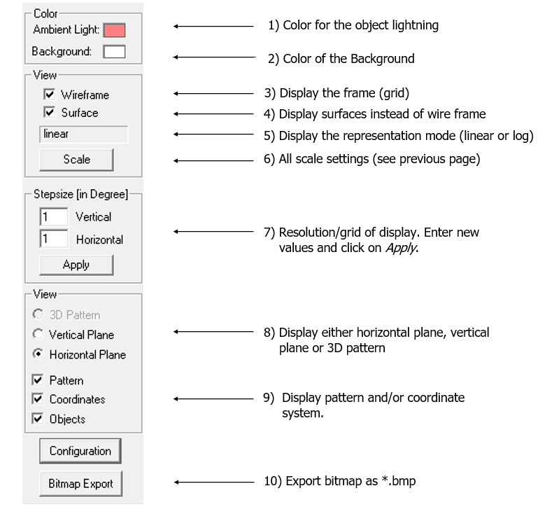
Figure 1. 3D control panel.
With the help of the control panel the display of the antenna pattern can be
controlled:
- The selection of the color to lighten the object is important to emphasize
details. Dark colors should be selected. Since the standard color of the surface
of the objects is red, the result on the display will not correspond exactly to
the selected color (it is a mix of red and the selected color).
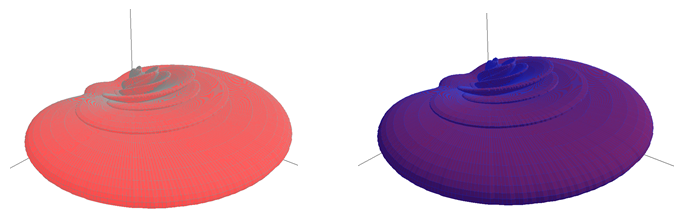
Figure 2. Different colors. - The background color used is always identical to the color selected (no color
mix). While for the printing of the graph, a white background is reasonable, a
more impressive result can be obtained with dark backgrounds.
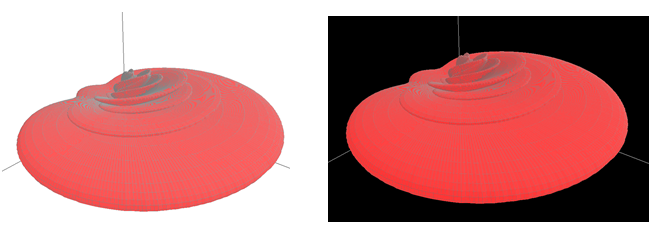
Figure 3. Different background colors. - To draw the antenna pattern with a wire frame, check the
Wireframe check box.
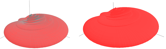
Figure 4. Same colors – but wire frame enabled (left) and disabled (right). - To draw the antenna pattern with filled surfaces instead of a wire frame, check
the Surface check box.Note: If filled objects are selected, the computing time increases.
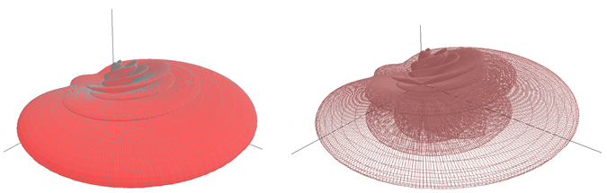
Figure 5. Same colors – but filled surfaces enabled (left) and disabled (right). - The program displays the type of scale selected (logarithmic or linear).

Figure 6. Everything identical except the linear (left) and the logarithmic scale (right). - All scale settings can be defined by clicking on the Scale button.
- Resolution of the display. The finer the value, the slower the display. A value
below 1° makes no sense as the finest resolution in the
pattern itself is 1°. To accelerate the display the
values can be set to 5°. This has no influence on the
data itself and its accuracy saved in the file.
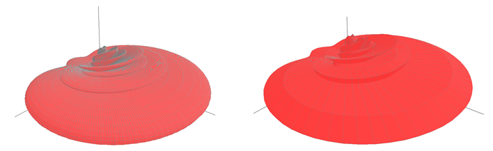
Figure 7. Everything identical except the angle increment: 1° (left) and 5° (right). - The pattern can be displayed either in 3D mode, or the vertical and horizontal
planes can be displayed. The user has to select the view with the radio
button.
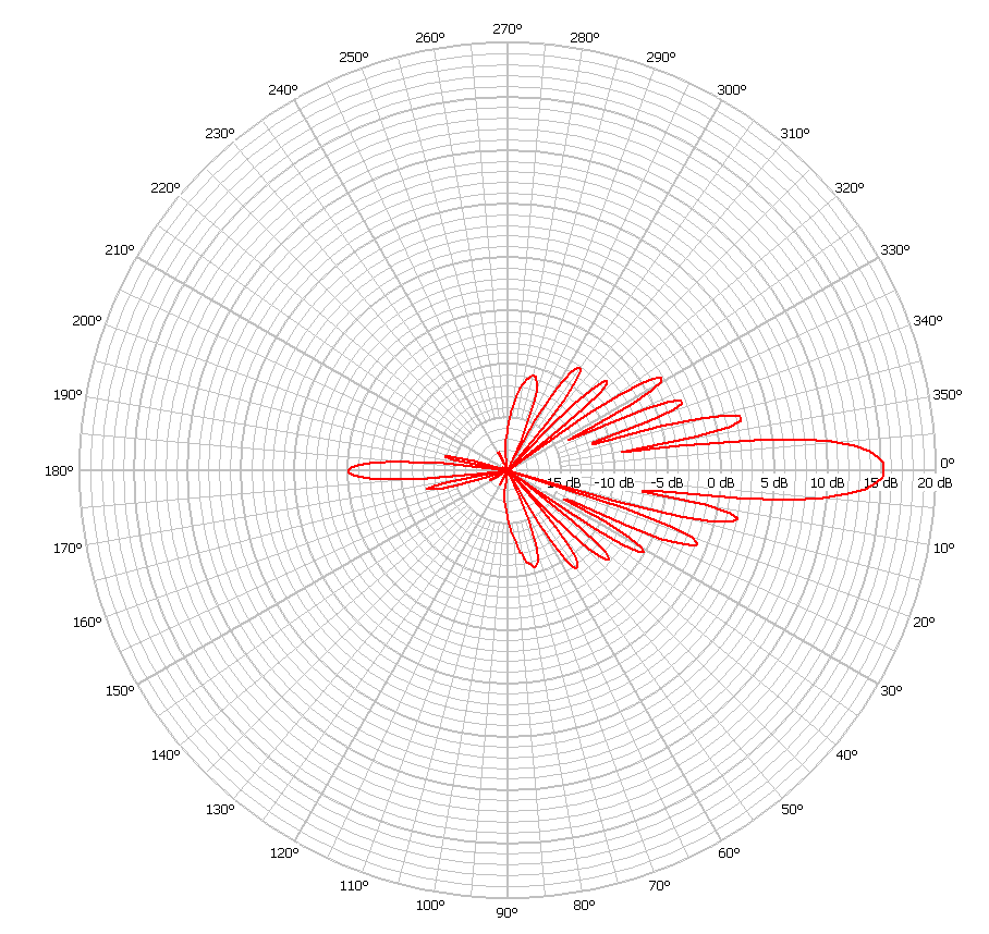
Figure 8. Vertical plane.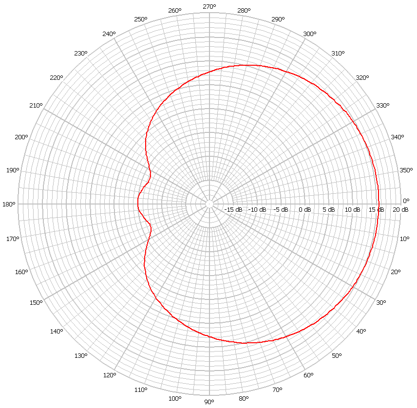
Figure 9. Horizontal plane.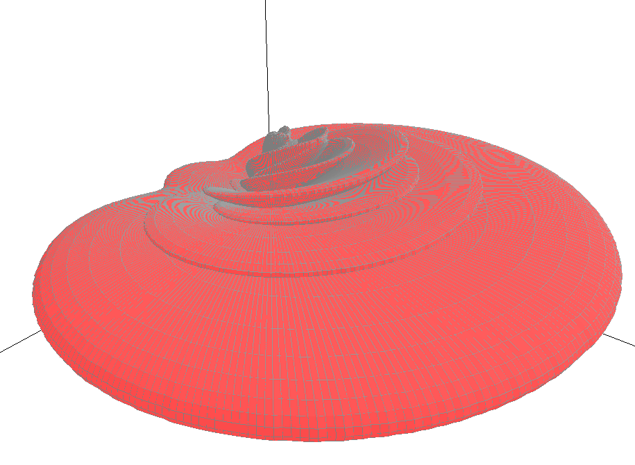
Figure 10. 3D view - The user can select if the pattern and the coordinate system should be displayed or not. This is especially important for the MASC module.
- You can export the display to a bitmap.