Rural, DTR
Calculate propagation in a rural scenario using the deterministic two ray model (DTR).
Model Type
In this rural/suburban scenario, the geometry is described by topography (elevation) and clutter (land usage).
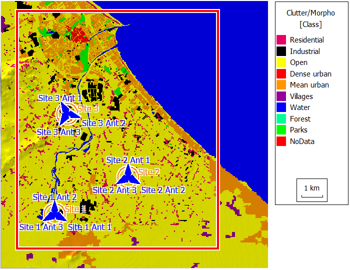
Figure 1. Topography for the rural area.
Sites and Antennas
Computational Method
The deterministic two ray model (DTR) model computes the direct ray and the ground reflected ray with ray optical algorithms. If a ray is shadowed by obstacles, it is not considered.
Figure 1 shows a prediction with the DTR method in a coastal area scenario. The received power is only predicted for pixels which can be reached by the direct ray and/or the ground reflected ray. All pixels in areas without line-of-sight to the transmitter are not predicted.
Results
Results are computed for each transmitter at a prediction plane of 1.5 m. Propagation results include power coverage of each transmitting antenna, field strength, and path loss for all three sites. An example is shown in Figure 2. White pixels are not computed because there is no line-of-sight between the transmitter and the pixel.
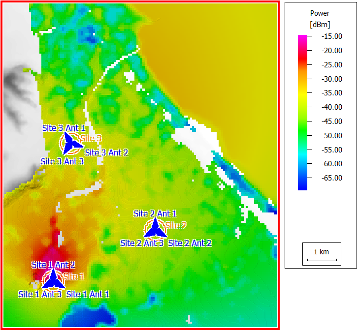
Figure 2. Power coverage of Site 1, Antenna 2.