Refinement Zones for Passenger Vehicles
In this section, we will dive into the resolution best practice for passenger-type vehicles. We will divide the passenger vehicle best practices into:
- General best practices
- Hatchbacks/Compacts
- Sedans/Coupes
- SUVs/Vans
- Pickup Trucks
Far field element size and used refinement levels
The simulation uses Refinement Levels (denoted RL), in which the cell size is halved each time the RL increases. This increases the cell count in each direction by a factor of two, and thus a factor 8 in 3d space. As each halved cell also doubles the time-step count per same physical time, the total computational load for a section by increasing the RL level is a factor 16. The far field element size (unit m) defines the largest element size in the model and is set in the .xml file or the inside the VWT. All additional mesh controls are defined relative to the far field size.
With a recommended far field voxel size set to 0.192 meters (192 mm), the following refinement levels will suffice for external aerodynamic simulations:
- RL 0: 192 mm
- RL 1: 96 mm
- RL 2: 48 mm
- RL 3: 24 mm
- RL 4: 12 mm
- RL 5: 6 mm
- RL 7: 1.5 mm
- RL 8: 0.75 mm
Please note that RL6 (3mm) is the Refinement Level that will be used on the whole vehicle for standard passenger vehicles, with local detailing sometimes at a higher RL than that. Therefore, RL6 and RL7 are important reoccurring Refinement Levels.
Types of refinement
- Refinement boxes
- Custom refinement zones
- Offset refinement zones
- Overall offset
- Offset per part
Refinement boxes are axes aligned and defined by minimum and maximum length in each direction (x,y,z).
Custom zones are defined using a closed part in the .stl geometry file, with resolution set inside that part. Please note that these custom zones need to be present in the main .stl file that contains the vehicle. Also note that if the custom zones are not defined but the part is present in the .stl file, any custom zone part will be regarded as having a solid wall. It is therefore important to check that all custom zones are properly defined in the .xml deck or in VWT.
Offset zones are defined using an offset length and Resolution Level. Please note that ultraFluidX will generate a minimum of 4 voxels regardless of the offset length setting. If no part is assigned for an offset, it will be applied to all solid surfaces. If a part is assigned, the offset will only be applied to that particular surface. An offset instance can have multiple parts, and a part can have multiple offsets overlaid on each other. The finest RL setting will have precedence in that case, so if multiple layers are build up with decreasing RL, the coarser ones will need to be defined with an additional offset length of all underlying higher RLs. For example if one wants 4 layers of 1.5mm RL7 and 12 layers of 3mm RL6 on top, the offset lengths would be 4*1.5=6mm for RL7 and 6mm+12*3mm=42mm for RL6.
In the sections below, these 3 types of Refinement will be used to capture relevant physics around the vehicle.
Note that in all passenger car sections, we will use versions of the DrivAer model for showing the resolutions (source TUMunich, https://www.mw.tum.de/en/aer/research-groups/automotive/drivaer/, allowance of usage greatly appreciated).
Vehicle refinement for outer regions (RL 1 through 3)
We will go through the resolution setup in steps, working our way in from the outermost resolution.
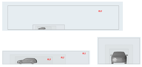
Figure 1. Outer domain RL0 and the first 3 RLs indicated on the DrivAer Estate model
It is recommended that RL1 is at least:
- X: 3 car lengths downstream, 1 car length upstream of the vehicle
- Y: at least one vehicle width off to the sides
- Z: at least one vehicle height above the vehicle
RL2 and RL3 are scaled down from there. It is recommended that RL3 end one car length behind the vehicle.
Refinement zones closer to the vehicle (RL4 and RL5)
Near the vehicle further, RL4 and RL5 are defined to capture:
- the underbody flow
- the wake
- the wheels
- the upstream boundary layer (in case of a VWT floor with a defined BL suction location)
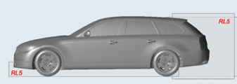
Figure 2. First two zones of interest to capture using RL5
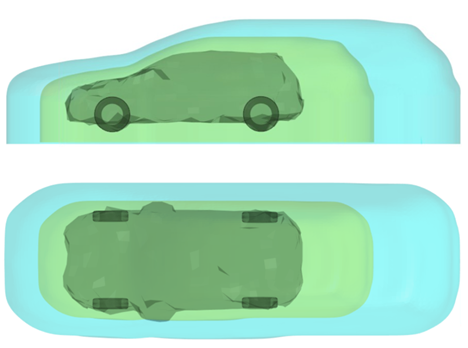
Figure 3. RL4 (blue) and RL5 (green) custom zones based on scaled wraps around a vehicle
Wind tunnel floor refinements
In the case of wind tunnel modeling, optional belts and a boundary layer suction location are present. In order to adequately capture the flow development in those regions, resolution needs to be placed correctly.
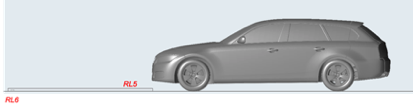
Figure 4. Resolution placement for the boundary layer suction device
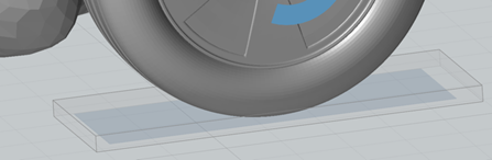
Figure 5. Refinement RL6 boxes around wheel belts
Custom refinements
In order to capture complex regions of high shear and separated flow, specific custom refinements are recommended around parts of the vehicle.
The recommended zones include (but not limited to):
- Nose of vehicle
- Air dams/spoilers
- Cowls
- A-pillar vortices
- Mirror wakes
- Wheels
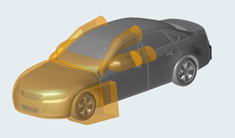
Figure 6. Example of custom refinement zones around the vehicle for capturing flow details
In the sections below, each custom refinement zone will be explained in detail.
- Mirror custom refinement
- The mirror needs special attention and two refinement zones need to be created. First, start by wrapping the mirror with a 12 mm convex wrap. Move the wrap rearward 100 mm and wrap the two wraps with a 12 mm convex wrap then scale this wrap by 105%. This will be a refinement zone of level RL6. Repeat the process by scaling the first mirror wrap by 120% and copying the wrap rearward 1.0 m and wrapping them with a 12 mm convex wrap. This wrap will become a resolution zone of RL5.
- Nose custom refinement
- Select the nose region and add surfaces in order to close the region. Loose wrap around the region, scaling and extruding down to the floor. This covers the engine bay and some wakes. It is recommended to set to RL5 (6mm) to capture the engine bay and the surrounding flow.
- Cowl and A-pillar custom region
- Create a simplified shape that generously covers any cowl vortex and separation/reattachment on the windscreen. RL6 is recommended.
Offset refinements
Now that separated flow regions are covered using custom zones and/or boxes, offsets regions are used to capture the boundary layer flow in regions of interest.
As mentioned, offset regions can be general on all parts (when no specific part is indicated) or on separate sections. The offsets are used to set resolution in the boundary layers on the vehicle in order to capture the necessary physics. As boundary layers are growing over the vehicle, we will see more placement of resolution on the upwind parts of the vehicle, where boundary layers are typically thinner. Also, separations and the effects of pressure gradients are important. Therefore, one will also see placement of resolution on parts that (possibly) separate, and rounded corners where large pressure gradients occur.
- General offset refinement on whole body
- As a starting point, for the general offset, 4 voxels (4x3mm=12mm) of
RL6 is recommended on the whole vehicle. Please note that in case of
scaling the far-field resolution, the offset distance needs to be scaled
to match 4 voxels again. This is true for both general and part
offsets.
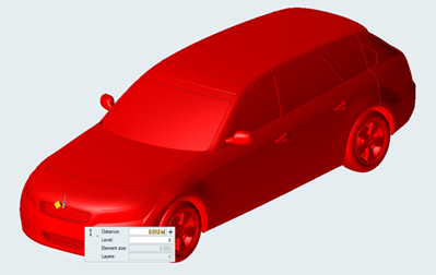
Figure 7. Whole body offset on all parts: RL6 4 voxels - Specific part offsets
- Next, specific part offsets need to be defined. The following regions are recommended for extra offset refinement:
-
All these areas are recommended to have: 4 voxels in RL7 (4*1.5mm=4mm) plus 12 voxels offset of RL6 over that (+12x3mm=+36mm for a total of 40mm RL6 offset)
On the last point, it is recommended to place additional resolution when investigating the effect of a specific part, for example a spoiler or lip.
The figure below shows some typical resolution placement for the front of the vehicle. The mirrors have thin boundary layers, changes in pressure gradients and separations, and are therefore part of the increased resolution sections. Next, the A-pillars are set to increased resolution, as formation of an A-pillar vortex is prone here. Note that the resolution definition stretches beyond the actual A-pillar part in both the upstream and downstream direction. It is recommended to isolate and include these sections as to have the resolution interface further from where the relevant physics occur. The nose of the vehicle is also covered, as there is a thin developing boundary layer all around, as well as pressure gradients. The tires are also set to a higher resolution, in part due to their curvature into the flow. Note that the lower bumper edge is indicated in a separate color. If the lower bumper has a sharp edge, separation may occur. It is recommend to further extend the RL7 offset on this part to capture the separated flow. The grill (in red) also needs attention, and is covered separately below.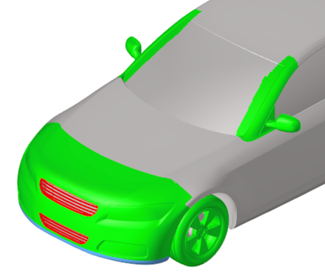
Figure 8. Example regions for partial offsets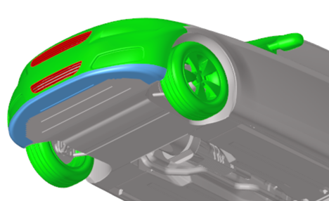
Figure 9. Lower bumper/air dam area offsetsDepending on the geometry, grills could need an offset of RL7 (1.5mm) or even RL8 (0.75mm) on grill elements to ensure enough voxels fit through the gaps. A bare minimum voxel count of 4 voxels is needed across a gap, with a recommended minimum of 6. Please note that this can be achieved using a simple offset on an isolated grill part.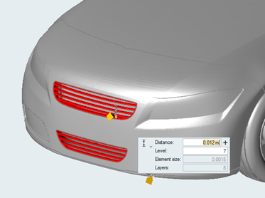
Figure 10. Possible grill offsetsThe separation location on the back end of the vehicles is important for capturing the right flow physics. It is recommended that the areas around the tail of the vehicle have an RL7 offset of 4 layers. The specific shape and location of these offset regions might differ by vehicle type. We will elaborate on the specific vehicle types below.
Wheels and tires
Parts that rotate are identified as wheels. There are two methods currently available to describe rotation in ultraFluidX. They are:
- Rotating walls
- Moving Reference Frame (MRF)
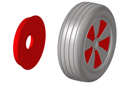
Figure 11. MRF zone created and its position with respect to the wheel spokes
Special preparations for fully treaded, deformed tires
Figure 12. Bottom view of deformed tire cut by a +1mm plane
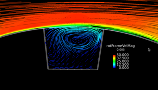
Figure 13. Example cavity flow when transformed in a rotating coordinate frame

Figure 14. Optional MRF (light blue) in tire treads, not needed in base Best Practice
Porous media and cooling flow
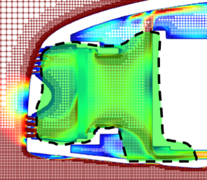
Figure 15. Cooling flow region in RL5, shown on DrivAer model
A minimum number of 6 voxels is recommended across the thickness of any porous media, where possible. Therefore, the cooling pack itself would often receive a box refinement of RL6 tight around the pack.
Consideration for Specific Vehicle Types
Considerations for hatchbacks/compacts/estates
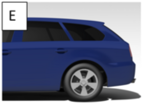
Figure 16. Estate (E) models are examples of mentioned geometry types in this section

Figure 17. RL7 regions on the tail end of hatchbacks, compacts, or estates
Note that the base does not need to be in RL7, which saves elements. Also note that the RL7 region extends past the separation edge as mentioned before. The shape of the RL7 region might not span a single part, but can wrap sections of adjacent parts as well. In the figure above for example, part of the rear glass is included in the region. Often taillights are in this zone. It is recommended to place the whole taillight unit in the RL7 region.
Considerations for sedans/coupes/fastbacks
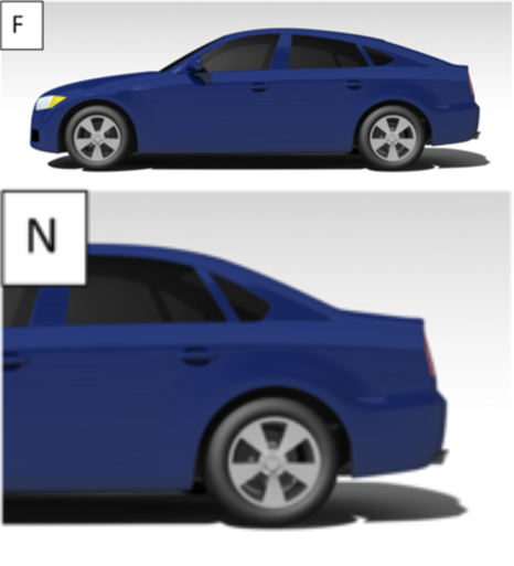
Figure 18. Fastback (F) and Notchback (N) models are examples of mentioned geometry types in this section
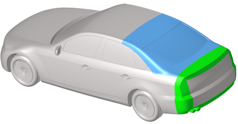
Figure 19. RL7 regions for consideration, known separation edges (green), adverse thickening boundary layers (blue)
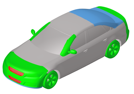
Figure 20. Complete offset strategy for the DrivAer sedan model
Considerations for SUVs/pickup trucks/vans
- Refinement zones
- Due to the increased sizes typically of SUVs/pickups/vans, the far-field resolution might need to be increased to have a reasonable cell count for the simulation. RL6 is 3mm on passenger cars, 3.2mm or 3.5mm RL6 is recommended depending on the size. For a 3.2mm setup for example, the resolution regions would look like this:
- Custom refinement cowl/A-pillar/mirrors
- When windscreens are more upright, a separation can occur upstream on the hood. Make sure that the cowl custom refinement region is enlarged to capture this phenomenon. A-pillar vortices and mirror wakes can be larger, enlarge the refinement regions and blend with overlap with the cowl and mirror wake regions.
- Truck beds
- Truck beds can have complex flows in them, where the flow from the cab interacts with the tailgate. It is recommended to add a region of RL5 surrounding the whole truck bed. Both the cab end, top of the tailgate area and sides of the truck around the taillights should have RL7 refinements as defined before (4x RL7 + 12x RL6), as the separation. The shear layer at the end of the cab should be captured in an RL6 custom refinement region for about 30cm, as well as the volume around the top of the tailgate.
In conclusion: general mesh setup for passenger cars
Based on the described best practice, a vehicle of 100-250 million voxels is created, depending on the vehicle details. A typical runtime of around 8 hours on Nvidia 8x V100 GPUs is estimated for 4 seconds of physical time using this scheme.