This section will describe the commercial heavy truck best practice setup. Note that
many of the logics and setup schemes are related to the passenger car setups. It is
recommended to first read through the passenger vehicle section.
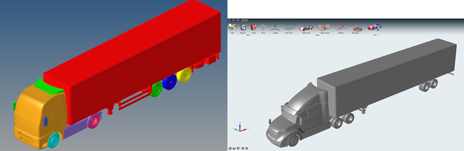
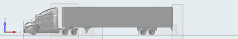
Commercial heavy truck best practices are divided into long-nose and cab-over
configurations due to their aerodynamic differences. Below, a general overview is
given, followed by specific pointers for long-nose and cab-over. Figure 1. Example commercial class 8 trucks. Left cab-over (Source FAT), right
long-nose (Altair demo truck)
Domain and resolution levels
The Resolution Level setup is adjusted to the increased size of commercial trucks,
keeping RL6 as the general offset on the whole vehicle region. Due to the larger
size, an RL6 of 6mm is recommended. This would give the following resolution
zones:
Refinement Level Vozel Size (mm):
RL 0: 384 mm
RL 1: 192 mm
RL 2: 96 mm
RL 3: 48 mm
RL 4: 24 mm
RL 5: 12 mm
RL 6: 6 mm
RL 7: 3 mm
RL 8: 1.5 mm
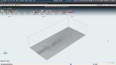
Note that due to the enlarged surface area, the domain dimensions need to be enlarged
to ensure a blockage ratio of less than 0.5%. Figure 2. Domain in VWT for a truck
As the proportions of a commercial truck including trailer differ, the following is
recommended for estimating the domain extensions:
Table 1.
Recommended domain size
tractor-trailer combination in lengths
+x
2
-x
4
+y
1 (or 12 widths)
-y
1 (or 12 widths)
+z
1.5 (or 20 heights)
VWT will create a default tunnel which is sized to provide a blockage ratio of 0.5%
and is adequate for standard open road simulations.
Vehicle box refinement for outer regions (RL 1 though 3)
For commercial trucks, the general resolution strategy for the outer 3 refinement
regions is similar, with a shift towards the rear of the tunnel to capture the wake
structures. In summary as before, it is recommended that RL1 is at least:
X: 3 vehicle lengths downstream, 1 vehicle length upstream of the
vehicle
Y: at least one vehicle width off to the sides
Z: at least one vehicle height above the vehicle
RL2 and RL3 are scaled down from there. It is recommended that RL3 end one length
behind the vehicle.
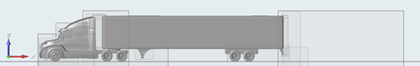
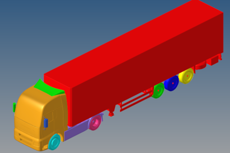
The outer resolution levels RL1- RL3 are thus large boxes encompassing the wake of
the truck, as seen in the figure below: Figure 3. Side view of the domain, depicted the creation of RL2 in yellow. Truck
and trailer indicated by the smaller RL zones
Major regions of resolution
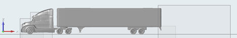
For the inner resolution levels, we will zoom in to specific parts and go through
them step by step. Figure 4. The inner resolution levels used below to describe best practices
setup
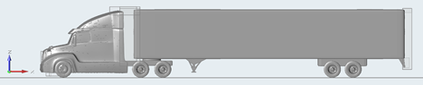
RL4 (24mm) is placed in the far wake of the trailer, the underbody flow over the
whole vehicle, around the tractor, and in the engine bay: Figure 5. Side view and top view of RL4 placement for trucks, covering engine bay,
tractor, underbody and wake
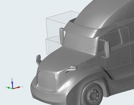
RL5 (12mm) is placed around more specific features, such as around mirrors (in
addition to custom zones), in the interface gap, around the trailer wheels and
landing gear, and in the near wake. Note the focus on the tractor to capture flow
features. Figure 6. RL5 placement example, covering cowl, mirrors engine bay, tractor
underbody, landing gear, trailer wheels, near wake, interface gap
Note that the cowl region is covered too: Figure 7. RL5 placement around main mirrors and cowl
RL6 is used around interface gaps, shear layers, cooling pack flow and bumper lower
shear layer. More details below. Figure 8. RL6 regions, cooling pack, bumper shear layer, interface gap at high
shear locations, separation shear layer at tail end of trailer
Note that the region around the porous media (including the post-PM flow) as well as
the bumper shear layer have dedicated regions to cover: Figure 9. RL6 regions further detailing
Offset refinement overall
The trailer and the aero surfaces will in general have an RL6 offset of 4 cells (4x
6mm). The engine bay and underbody in regions that do not directly touch the main
underbody flow can be in RL5 if needed for voxel count reduction. Specific regions
are selected for having RL7 and/or a larger number of RL6 offsets. These regions
will be defined in the long-nose and cab-over sections of this chapter.
Refinement details for all trucks
The following refinement boxes or custom regions are recommended for all truck types.
Please note that it is geometry dependent whether a box or a custom region is
needed. Also note that some regions have already been mentioned.
Tractor-trailer interface gaps
The shear layer in the tractor-trailer as well as inter-trailer gaps is
important and needs to be resolved in RL6 (6mm). If the geometry is axis
aligned such that a box region suffices to capture the shear layer, this
is ok. Else a custom region can be created out of a simplified shape,
like a morphed shape. Figure 10. Regions in the interface gaps that need to be covered, in
green
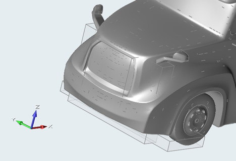
Trailer base
The base of the trailer needs to be covered all around (top, sides,
bottom including bars) using refinement boxes in RL6. This should cover
the boundary layer and the separating shear layer over the edge for the
first 0.4m. Figure 11. Resolution coverage at the base of the trailer, not the
finest region around separation
Shear layers off the front bumper
At the bottom of the front bumper, the flow typically separates, and the
shear layer is interacting with the underbody elements of the tractor.
This shear layer should be captured in RL6 using a custom refinement
zone. Any element that is impinging the main flow should have 8 x RL6
offset voxels as well for the first 2m underneath the tractor. Figure 12. Custom zone for capturing the shear layer off the front
bumper (in green), and offsets needed for impinging parts
(example at green arrow)
Cooling pack flow
The flow through the grill elements and past the cooling pack is
important. Use either a box or custom refinement region to capture this
flow at least in RL5, preferably RL6.
Treatment of the wheels
Commercial trucks typically have more closed rims compared to passenger
vehicles. For that reason, an MRF setup is not needed, and a moving wall
boundary condition suffices for the rims, axles, brakes and tires.
The flow around the wheels is important, especially the front axle; the
first tractor rear axle and the first trailer rear axle can receive a
lot of flow. It is recommended to use on the front tires: 8 layers of
RL7 (3mm) plus 12 layers of RL6 on top of that. This can be repeated for
the other axles. If voxel count needs to be reduced, remove the RL7 of
any tires that are not leading into the wind, and focus on the tractor
wheels only.
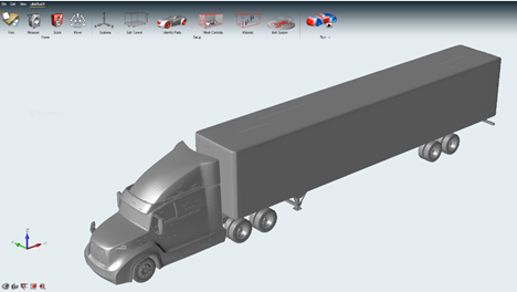
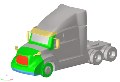
Considerations for long-nose trucks
Figure 13. Example long-nose truck using the Altair Truck
Custom refinement regions
It is recommended to create the following custom refinement
regions:
around the nose including the lower bumper
specific wake of lower bumper deflector
zone around the mirrors
cowl vortex region
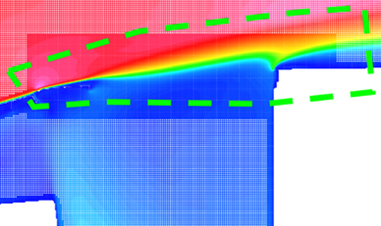
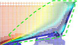
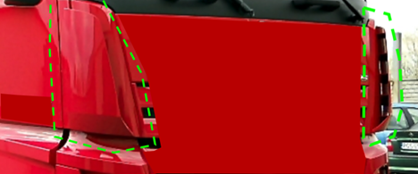
The cowl vortex on the hood of a long-nose truck can be quite large due
to the large angle between the hood and windscreen. It can extend
forward of the windscreen. This vortex needs to be captured with a RL5
region box or shaped custom refinement zone. This zone needs to extend
to the mirror section of the truck on the sides, as the cowl vortex
commonly interacts with the flow around the mirror. Figure 14. Example of why resolution is needed in the cowl zoneThe green dotted line indicates needs for added refinement due
to the separation and forming of a cowl vortex. Figure 15. Example custom zones for long nose truckNote that the cowl region is not included here as it was set
as a box region separately afterwards
For the offset zones, as with the general setup, focus on the nose of
the tractors, the region around the wind screen and mirrors, and rounded
edges that could separate, underbody parts in the main flow, and aero
features such as deflectors. Optional elements such as detailed grids
and surfaces that possibly have separation bubbles can also be
considered. Figure 16. Examples of focus for offset regions in RL7General zones in green including nose and a-pillar, lower
bumper separation zone offset in blue, critical appendages in
yellow. Note the grill in red, which might need even additional
resolution depending on the grill elements sizing.
Considerations for cab-over commercial trucks
Figure 17. Example cab-over truck (Source FAT)
Air curtain
Cab-over trucks typically can have a flow deflector around the front
corners to prevent soiling onto the side-glass and door handles, called
an air curtain. Figure 18. Air curtains on cab-over trucks
This air curtain contains slots to pass flow through. A minimum of 6
cells in these slots is recommended, resulting in the use often of a RL7
(3mm) or even RL8 offset region.
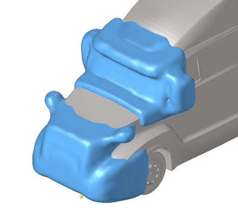
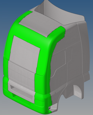
Leading edge corner flows
For cab-over trucks, the flow around the leading-edge corners is
important. It is suggested to isolate the parts over the full height and
set a part offset of 8 layers RL7 (3mm) plus an offset of 8 layers of
RL6 (6mm) on top of that. Figure 19. Offset regions for leading edge corner flow on cab-over
trucks (model source FAT)
Also add similar offset regions to details in the flow, such as mirrors,
roof deflectors, flaps, and underbody parts in front in the main
flow.
Yaw-angle notes
The current best practices for the previous truck sections are set for 0-degree yaw
angle. However, for commercial truck applications, a yaw angle (for example, 5 or 10
degrees) can be an interesting case to investigate. The leeward side of the trucks
will have a large wake, which would be filled in from the top/bottom of the trailer,
from leeward edges of the tractor, and from cross-flow in the tractor-trailer
gap.
Considerations for yaw setups:
The leeward edges should have a shaped refinement zone to capture the
separation (RL6).
The wake on the leeward side should be adequately captured in RL5 and RL4.
This can be achieved using combined loose wraps of 0 yaw till max yaw
surfaces.
The tractor trailer gaps should have at least RL5 in the whole interface to
cover cross-flow.
Run-time of the simulation
A full tractor-trailer combination is typically a lot longer than a passenger
vehicle. 8 flow passes is recommended to settle the flow, and another 8 for
measurement of the required variables.
For example, for a 16m long combination, inflow 25 m/s, we have 25/16=1.6 flow passes
per second. The recommended setting would be:
Total simulation time 10s
Start of averaging time 6s (measuring between 5s and 10s)
In conclusion: mesh setup for commercial trucks
For 0 yaw, the current best practice should generate a setup of around 220-320
million voxels, which would run for 10 seconds physical time in less than 1 day on
Nvidia 8 x V100 GPUs.