Sketch Planes
Use the tools in the sketch toolbar to define the sketch plane and adjust the grid settings.
When in sketch mode, a sketch plane is displayed and is represented as a grid with major and minor lines.
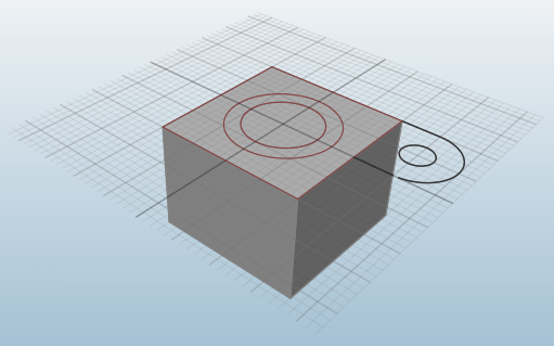
Figure 1. Sketch Plane
Tip: Click  in the view controls to rotate the model so that
the sketch plane is normal to the grid. Successive clicks will toggle back and forth between
fitting the entire model in the view and zooming in on selected sketch curves.
in the view controls to rotate the model so that
the sketch plane is normal to the grid. Successive clicks will toggle back and forth between
fitting the entire model in the view and zooming in on selected sketch curves.
Define the Sketch Plane
When a sketch tool is active, select a face to define the sketch plane.
Tip:
- Click New Plane
 to select a new sketch plane.
 - Click Move Plane
 to open the Move tool and translate or rotate
the sketch plane.
to open the Move tool and translate or rotate
the sketch plane.
Modify Grids and Grid Snaps
Adjust grid and grid snap settings using the Options tool on the Sketch toolbar.
Location: Sketch Toolbar
- Grid # spacing
- Change the default spacing for a grid. There are five progressive levels of grid spacing.
- Snaps every # fine grids
- Use to adjust snapping behavior for minor grid lines.
- Snap to grid
- Deselect to disable grid snapping entirely. Press ALT to tempoarily disable snapping.
- View normal to plane on create
- Automatically rotate your view when a sketch plane is created, so that the sketch plane is normal to the view.
Create 2.5D Sections
Extract sketch curves from optimized results.
Placing the sketch plane on an optimized part will automatically create 2D sketch geometry through the section plane. This works best with 2.5D (extruded) optimization results.