Sketch a bridge, create a design space, run an optimization and explore the optimized
shape.
In this lesson you will learn how to:
Use sketch tools
Apply supports
Apply a pressure
Apply symmetry
Define a design space
Run an optimization
Explore optimized shapes
Sketch a Rectangle and Pull into a Solid
Start Inspire. Or if it is already open, click the
New model tool on the File
icon.
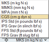
Click on the Unit System Selector in the lower right
corner of the modeling window, and change the display units to CGS
(cm g dyn s).
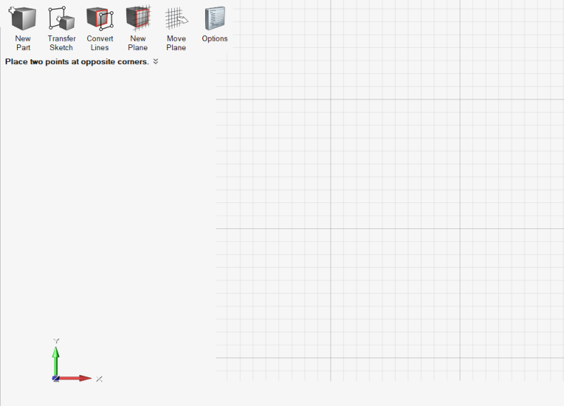
Select the Rectangle by Corners tool on the
Geometry ribbon.
A sketch plane appears.
Zoom out using the scroll wheel on the mouse.
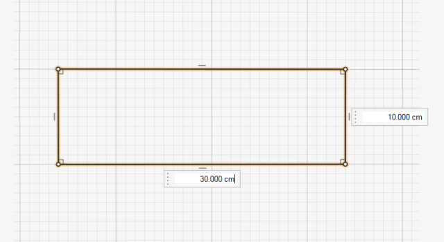
Draw a rectangle by clicking the left mouse button once
to place the first corner, and a second time to place the opposite corner, so
that the dimensions of the rectangle are 30 cm by
10 cm.
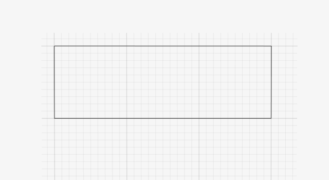
Right-click and mouse through the check mark to exit, or double-right-click.
Double-right-click again to exit sketch mode and enter push/pull mode.
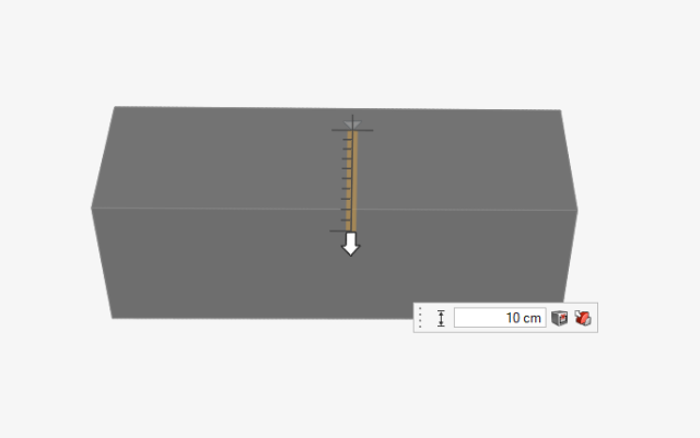
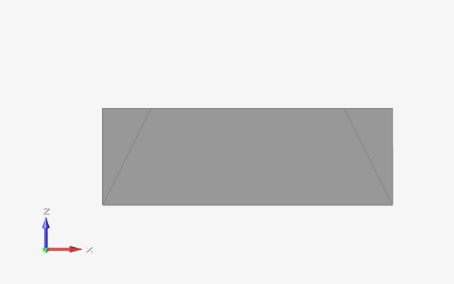
Use the middle mouse button to rotate the model forward
slightly, then click and drag with the left mouse button
to pull the rectangle into a solid 10 cm thick.
Double-right-click to exit push/pull mode.
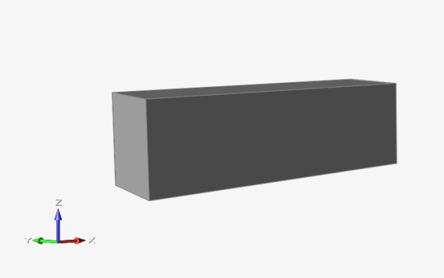
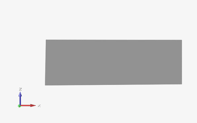
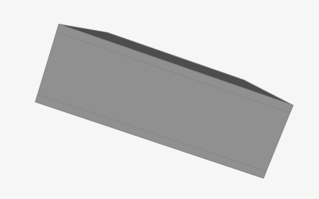
Click and drag with the middle mouse button to orient
your model so that the z-axis is in the vertical direction, as shown
below:
Use a Closed Curve to Create a Hole
Select the Rectangle by 3 Pts tool on the Geometry
ribbon.
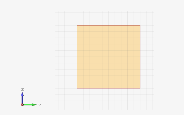
Click on the square end of the solid to select the sketch plane.
Use the middle mouse button to rotate and adjust the
view as shown:
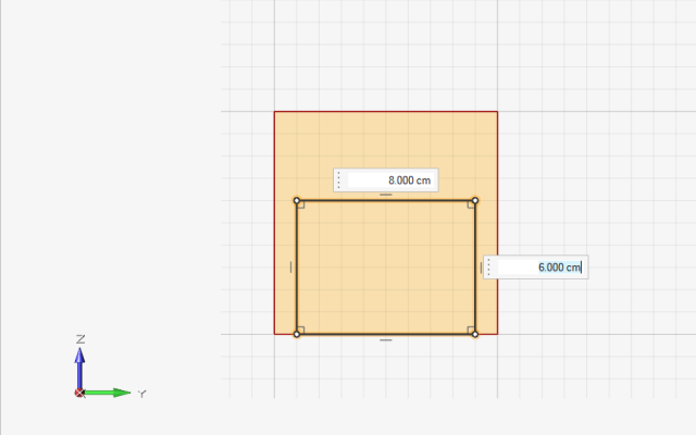
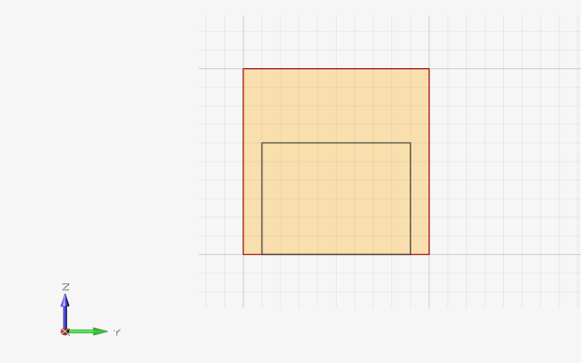
Draw a rectangle by clicking the left mouse button twice
to place the bottom two corners, and a third time to place the center of the
opposite side, as shown in the video above. The rectangle should be 6
cmtall and 8 cm wide and positioned along
the bottom edge of the solid.
Right-click and mouse through the check mark to exit, or double-right-click.
Double-right-click again to exit sketch mode and enter push/pull mode.
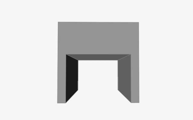
Click and push on the subface with the left mouse button
to push a hole through the solid.
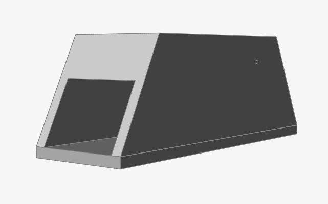
Double-right-click to exit push/pull mode, and use the middle mouse
button to orbit the model.
Use Open Curves to Trim the Solid
Click the Rotate to Closest Principal Axes icon at the
bottom left corner of the modeling window, then use the scroll
wheel to zoom out and the mouse controls
to adjust the view as shown.
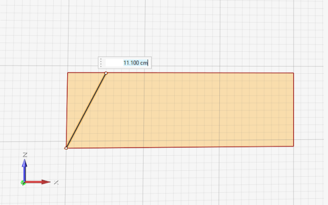
Select the Lines tool on the Geometry ribbon.
Click on the solid to select the sketch plane.
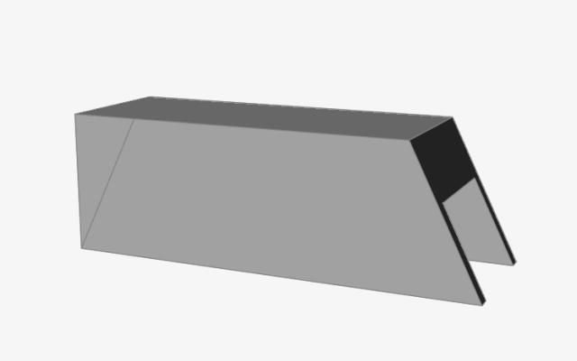
Draw a line by clicking the left mouse button twice to
place the end points, one at the bottom corner and another 5
cm along the top edge, as shown below. (The length of the line
will be about 11.1 cm.)
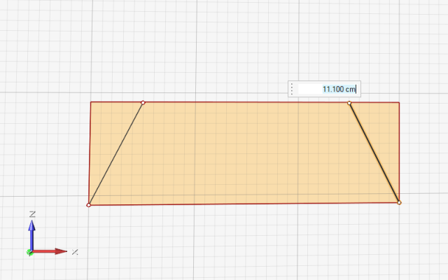
Draw a second line on the opposite side of he rectangle, indented 5
cm along the top edge, as shown below:
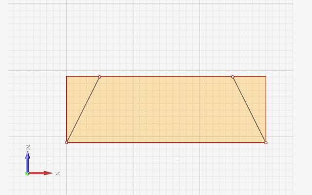
Right-click and mouse through the check mark to exit, or double-right-click.
Double-right-click again to exit sketch mode and enter push/pull mode.
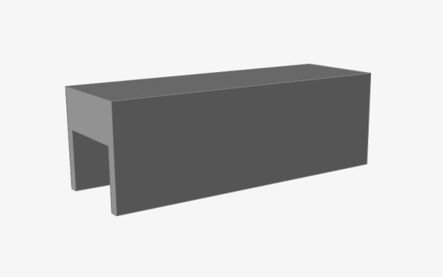
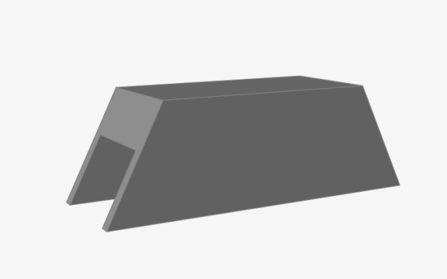
Click and push one of the triangular subfaces with the left mouse
button to trim the solid.
Click and push the other subface with the left mouse
button to trim the opposite side.
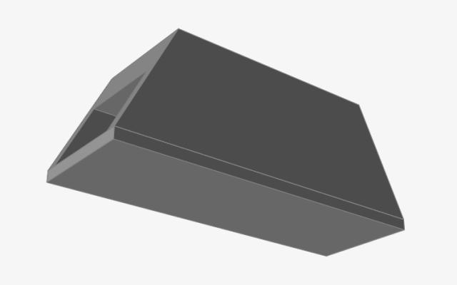
Double-right-click to exit push/pull mode, and use the middle mouse
button to orbit the model.
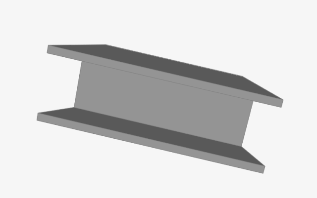
Create a Rectangular Base for the Bridge
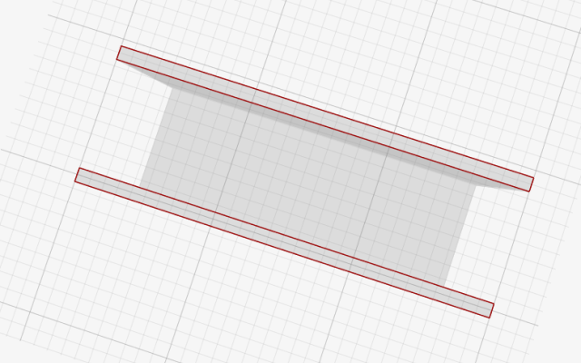
Using the middle mouse button, rotate the model so you
can see the bottom of the bridge, as shown below:
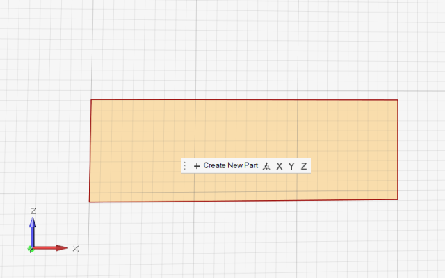
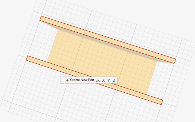
Select the Rectangle by Corners tool on the Geometry
ribbon.
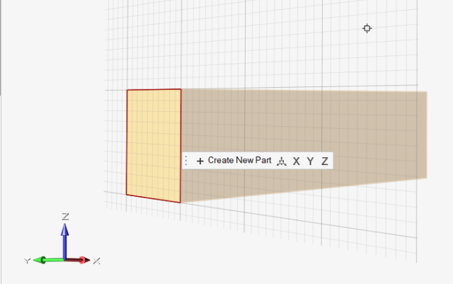
Click on one of the bottom faces to select the sketch plane.
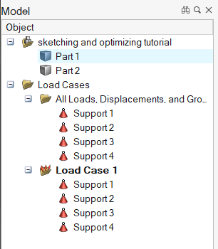
Click the Create New Part button on the microdialog. A
new part appears in the Model Browser, and the geometry you are about to create
will be placed in that new part.
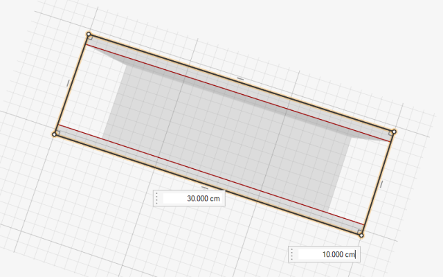
Using the left mouse button, draw a 30
cm by 10 cm rectangle on the bottom face
by placing two opposite corners, as shown below:
Right-click and mouse through the check mark to exit, or double-right-click.
Double-right-click again to exit sketch mode and enter push/pull mode.
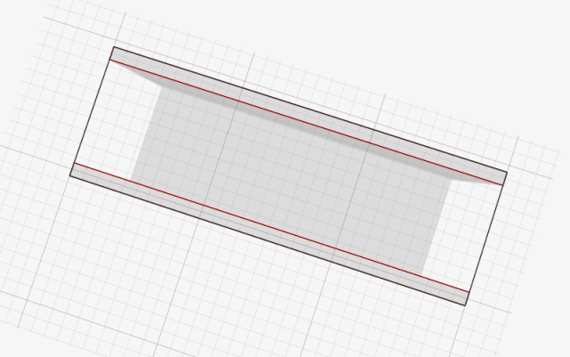
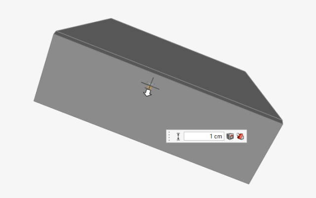
Click and drag with the left mouse button to pull the
rectangle into a solid 1 cm high. (Alternatively, you can
enter 1.0 in the text field and press
Enter.)
Double-right-click to exit push/pull mode, and use the middle mouse
button to orbit the model.
Apply Supports
Adjust the view so you can see all four corners of the bottom face.
Select the Apply Supports tool from the Loads icon on
the Structure ribbon.
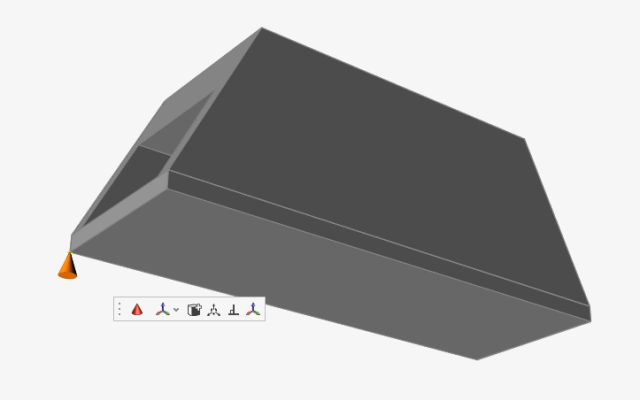
Move the mouse cursor over the leftmost corner until the cursor hint displays a
point support.
Left-click on the corner to apply the support, which is shown as a cone.
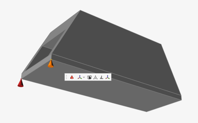
Click on the left front corner to apply another point support.
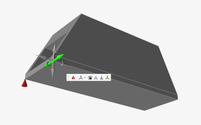
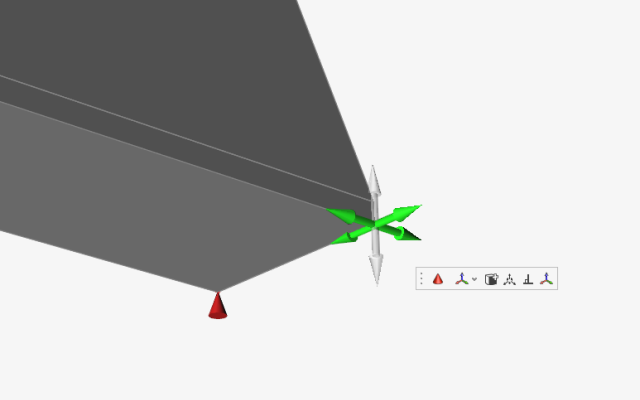
Double-click the support cone. Three clear axes appear, indicating the
translation is locked in all three directions. Click on the axis shown below to
enable translation in that direction. (The axis will turn green when selected
and is toggled on and off with each successive click.)
Double-right-click to exit and left-click to deselect. The support cone now has
green rollers, indicating that the support is free to translate in one
direction.
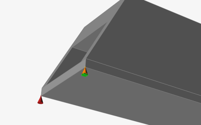
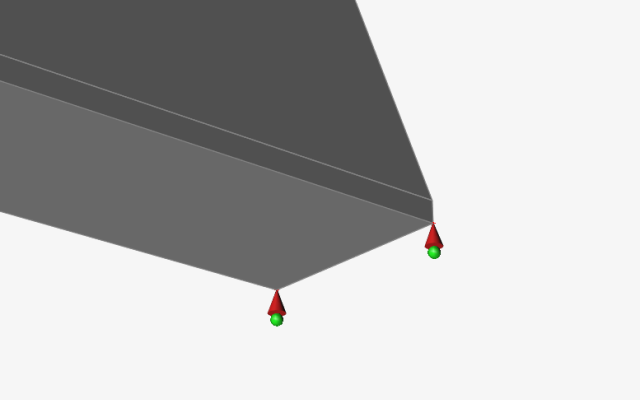
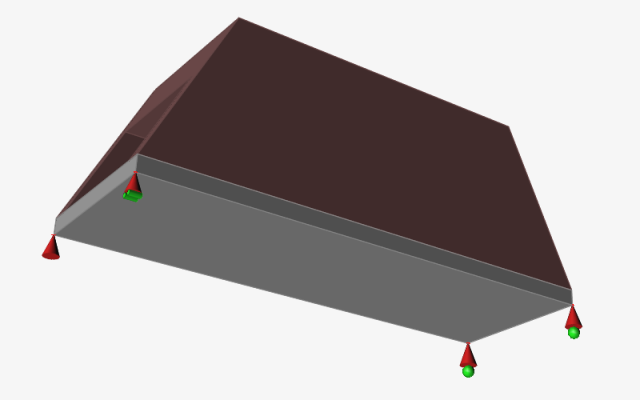
Apply point supports to the other two corners. Double-click the support cones
and select the axes shown below, so that they are free to translate in two
directions.
Double-right-click to exit and left-click to deselect. The red support cones
now display green balls, indicating that the supports are free to translate in
two directions.
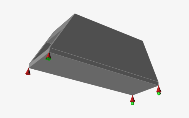
Zoom out and adjust the view. Your model should appear as shown below:
Define a Design Space
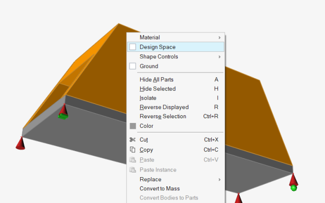
Right-click on the bridge part. The selected part turns yellow, and a context
menu appears.
Select Design Space from the menu. Any part that is
defined as a design space will generate a new shape when you run an
optimization.
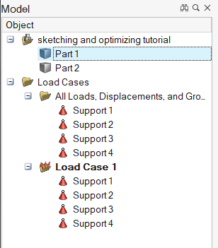
If not already visible, press F2 to open the Model
Browser.
While the bridge part is still selected, select Part 1
in the Model Browser. The text field becomes editable.
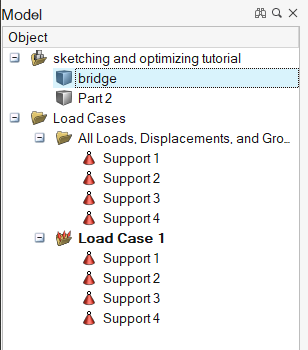
Type "bridge" and press Enter to rename the part.
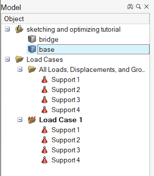
Select Part 2 and rename it "base" in the Model
Browser.
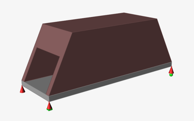
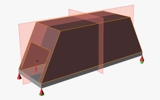
Left-click on an empty space in the modeling view to deselect the part. The
bridge part is now a design space and is displayed with a reddish-brown color
when not selected.
Apply a Pressure
Adjust the view so your model appears as shown below:
Select the Apply Pressures tool from the
Loads icon on the Structure
ribbon.
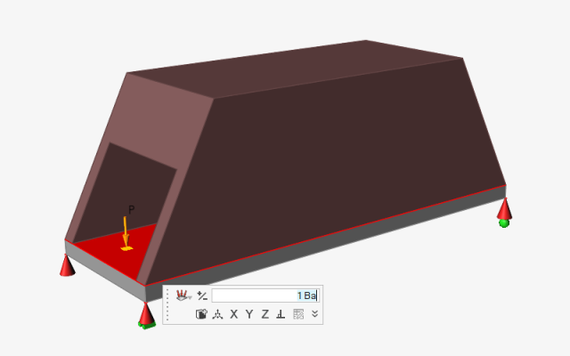
Move the mouse cursor over the base and apply a pressure by left-clicking the
top face.
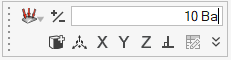
A microdialog for the pressure appears, allowing you to change the direction or
magnitude of the pressure. Type 10 Ba in the text field
and press Enter.
Right-click and mouse through the check mark to exit, or double-right-click.
Apply a Shape Control
Select the Symmetry tool from the Shape Controls icon on
the Structure ribbon.
A secondary ribbon appears, and the Symmetric tool is
selected by default.
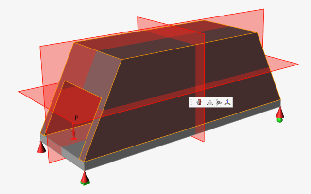
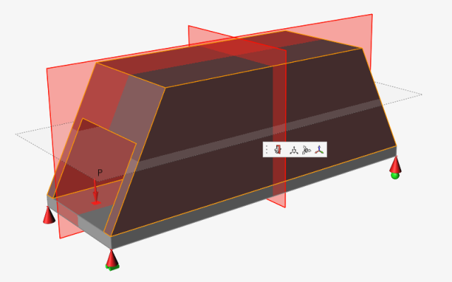
Left-click the design space. Three symmetry planes appear in red, indicating
they are all active.
Clicking on a symmetry plane toggles the plane on and off. Deselect the
horizontal plane shown below, so that the plane appears transparent.
Right-click and mouse through the check mark to exit, or double-right-click.
Run Optimization to Generate Shapes
Select the Run Optimization tool on the Optimize icon on
the Structure ribbon.
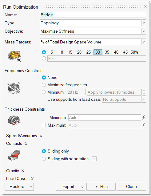
The Run Optimization window appears.
Select Maximize Stiffness for the optimization
Objective.
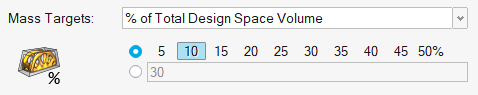
For Mass targets, make sure that the % of
Total Design Space Volume is selected in the pull-down menu, and
select 10 to generate a shape using 10% of the material
in the design space.
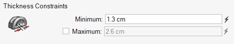
Under Thickness constraints, change the
Minimum to 1.3 cm.
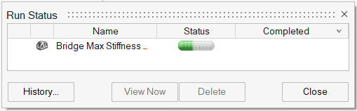
Click the Run button at the bottom of the window to run
the optimization. The Optimization Run Status window
appears and displays a progress bar for the run. (The number in parentheses is a
counter that increments each time you run a new optimization.)
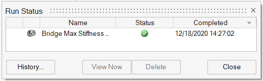
When the run has completed successfully, its progress bar is replaced by a
green circle.
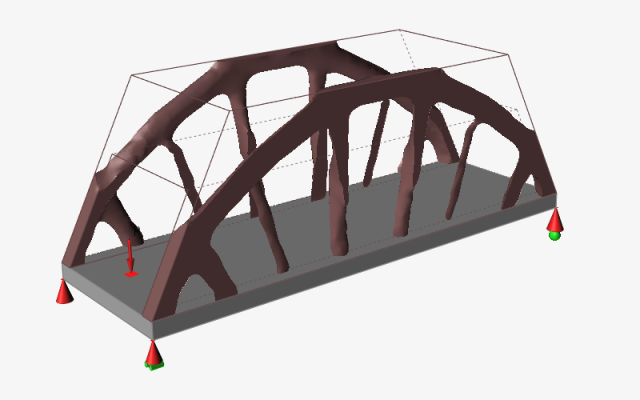
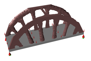
Double-click the name of the run in the Run Status
window. The generated shape appears in the modeling window.
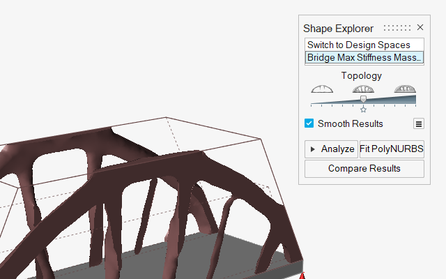
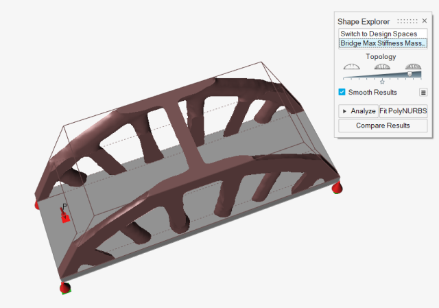
Explore the Optimized Shapes
When you first view an optimized shape, the Shape
Explorer appears in the top right corner of the modeling
window.
Adjust the view to get a better view of the top of the bridge.
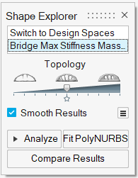
Click and drag the Topology slider in the
Shape Explorer to add or subtract material from the
design space.
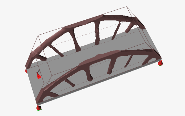
Notice that as you increase the amount of material, new geometry across the top
of the bridge emerges. This is an indication that you may need to rerun
optimization at a higher percentage for % of Total Design Space
Volume.
Select Switch to Design Space in the Shape
Explorer to view the original design space. If you exit the
Shape Explorer, you can always view the shape
generated from the most recent optimization run by clicking the bridge on the
Optimize icon.
As you make more optimization runs on this part, each additional run will
appear in the Shape Explorer list. Click on a run in the
list to view the optimized shape for that run.
To save and export an optimized shape, refer to the Saving and Exporting Files
tutorial.

 A sketch plane appears.