Cyclic repetitions are valid for optimization but not analysis.
You can generate cyclically repeating shapes like starfish, propellers, or spoked wheels
even if you use a design space or loads that are not cyclic themselves. There are two
kinds of cyclic shapes: those with symmetric sectors and those with asymmetric sectors.
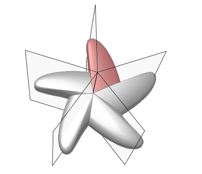
The Cyclic tool is used to create asymmetric sectors, as shown below. (Use the Cyclic
Symmetric tool to create symmetric sectors.) Figure 1. Cyclic repetition with asymmetric sectors
To enforce cyclic repetition on a design space, you specify a center line and the number
of repetitions to create within a 360 revolution. Red edges appear on cyclic repetition
planes to indicate symmetric sectors and black edges to indicate asymmetric sectors, as
shown above. You won't usually generate perfectly cyclic shapes, but you will get nearly
cyclic shapes.
Apply Cyclic Repetition
Select a design space and the number of cyclic sectors.
Click the Symmetric tool on the Shape Controls
icon.
Click the Cyclic tool on the secondary ribbon.
If you selected a design space before invoking the tool, cyclic repetitions are
automatically applied to that design space. Otherwise, click on a design space
to apply a cyclic constraint.
A microdialog and a set of three black radial planes
appear.
Specify the number of Sectors in the text field of the
microdialog.
Right-click and mouse through the check mark to exit, or double-right-click.
Microdialog Options
Double-click a shape control to edit it and access the microdialog
options.
Icon
Description
Apply Symmetry and Cyclic Repetition
Click to convert to a different type of shape control.
Sectors
Enter the number of cyclic sectors.
Translate or rotate the shape control.
Align the radial planes to the global x, y, or z direction.
Align a shape control to a design space after moving it. By default,
the radial planes are positioned and aligned to capture the natural
shape and orientation of the design space, however it is oriented in
space.
Click to manually enter the x, y, z components of the direction
vector.