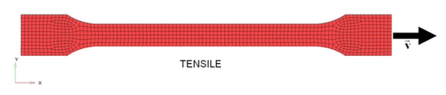
This tutorial demonstrates how to simulate a uniaxial tensile test using a
standardized specimen with a defined cross-sectional area which is stretched until
fracture.
The tensile test is a standardized method of material testing to determine the yield
strength, tensile strength, elongation at break and other material parameters. It is
one of the quasi-static, destructive test methods. Figure 1.
The model description is as follows:
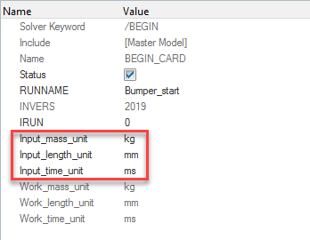
UNITS: Length (mm), Time (ms), Mass (kg), Force (kN) and Stress (GPa)
Simulation time D01 [0 – 40.]
At the right side, a constant velocity is applied = 1 mm/ms on -X
direction.
Tensile test object dimensions = 12 x 200 with a uniform thickness = 1.7
mm
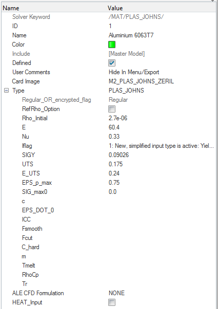
Johnson-Cook elastic plastic material /MAT/PLAS_JOHNS (Aluminum
6063 T7)
[Rho_I] Initial density = 2.7e-6Kg/mm3
[E] Young's modulus = 60.4 GPa
[nu] Poisson's ratio = 0.33
[SIGMA_Y] Yield Stress = 0.09026 GPa
[UTS] Ultimate Tensile Stress = 0.175 GPa
[E_UTS] Engineering strain at UTS = 0.24
[SIG_max] Maximum Stress = 0 GPa
[EPS_max] Failure Plastic Strain = 0.75
Input file for this tutorial: tensile_start_0000.rad
Load the Radioss User Profile
Launch HyperMesh Desktop.
From the Preferences menu, select User Profiles or click
the
icon in toolbar.
Select Radioss (Radioss2021)
and click OK.
Import the Model
Click File > Import > Solver Deck or click .
Click the Select File icon to open the tensile_start_0000.rad file you saved to your working directory
from the radioss.zip file.
Click Open.
Click Import.
Ignore the warning “No valid Engine File
found…”
Click Close to close the window.
In the Model Browser, verify that the correct units are
defined by expanding Cards, BEGIN_CARD.
Figure 2.
Create the Material
In the Model Browser, right-click and select Create > Material.
In the Entity Editor, for Name, enter
Aluminum 6063T7.
Set Card Image to M2_PLAS_JOHNS_ZERIL.
Click Yes on the pop-up that warns of a card image
change.
In the Entity Editor, input the values, as shown in the
following image.
Click on the component, Tensile_coupon.
In the Entity Editor, for Mat_Id, click twice on
Unspecified and select the newly created
material.
Click OK.
Figure 3. Material card of component Tensile_coupon
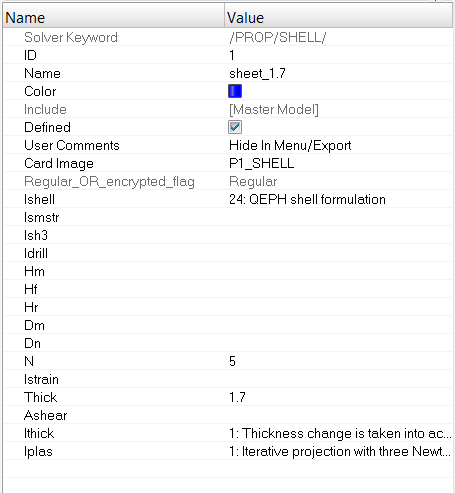
Create the Property
In the Model Browser, right-click and select Create > Property.
For Name, enter sheet_1.7.
For Thick, enter 1.7. in the Value field corresponding
to sheet thickness.
In the Entity Editor, input the values, as shown in the
following image.
Click on the component, Tensile_coupon.
In the Entity Editor, for Prop_Id, click twice on
Unspecified and select the newly created
property.
Click OK.
Figure 4. Property Card of Component Tensile_coupon
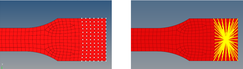
Create the Rigid Body
In the Model Browser, right-click and select Create > Component.
In the Entity Editor, for Name, enter Rigid
Body.
Set Card Image to None.
From the Mesh pull-down menu, select Create > 1D Elements > Rigids.
Set Secondary node(s) (nodes2-n) to Multiple Nodes.
Set primary node to Calculate Node.
Click Nodes and select the nodes as shown in Figure 5.
Click create and return.
Figure 5. Selection of the secondary nodes of the rigid
body
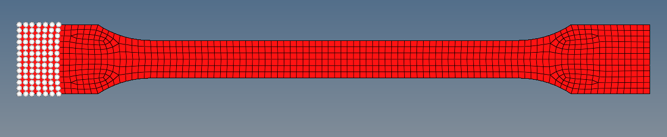
Create the Boundary Conditions
Select View > Solver Browser, and right-click in the Solver tab
area.
Select Create > BOUNDARY CONDITIONS > BCS.
For Title, enter constraint1 and right-click
grnd_ID and click
Create.
Within the grnd_ID section, click on 0
Nodes beside Entity IDs, then
Nodes.
A nodes selection appears.
Select the nodes, as shown below and
click proceed.
Figure 6.
Check the box beside DOF1, DOF2, DOF3, DOF4, DOF5, and DOF6 to fix all the
degrees of freedom.
Right-click BCS > Create to create a second constraint for the Rigid Body.
For Title, enter constraint2.
Right-click grnd_ID and select
Create.
Type “o” for options and select graphics > coincident picking to select the main node of the Rigid Body.
Within the grnd_ID section, click 0
Nodes beside Entity IDs, then
Nodes.
A node selection appears.
Select the node 990, as shown below and click
proceed.
Figure 7.
Activate all degrees of freedom, except of DOF1, translation in the
X-direction.
Create the Imposed Velocity
Select View > Solver Browser, and right-click in the
Solver tab area.
Select Create > BOUNDARY CONDITIONS > IMPVEL.
For Title, enter imposed_velocity and
right-click grnd_ID and click
Create.
Within the grnd_ID section, click on
0 Nodes beside
Entity IDs, then
Nodes.
A nodes selection appears.
Click node 990 to select the main node
of the rigid body and click
proceed.
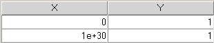
Right-click on fct_ID(T) and select
Create.
Right-click on fct_ID(T) and select
Plot Curve.
An XY curve editor appears.
Enter the values, as shown in the table below.
Figure 8.
Click Update to update the curve with
the new values.
Click Close to close the Curve editor.
The created curve is assigned to this
constraint.
Create Time History Output
In the Solver Browser, right-click Create > TH > RBODY
In the Entity Editor, for Name enter
TH_RBODY.
For Entity ID’s select Elements, select the
Rigid Body and click
proceed.
Set NUM_VARIABLES to 1 for DEF (default).
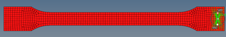
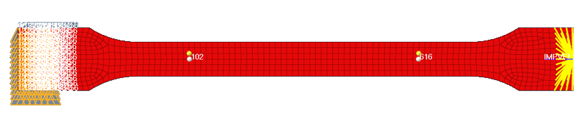
From the Geom page, select temp nodes. Pick two nodes
(yellow) with a distance of 80 mm .
Figure 9. Temporary nodes with a distance of 80mm
In the Solver Browser, right-click Create > TH > NODE.
In the Entity Editor, for Name enter
TH_Measuring_Nodes.
For Entity ID’s select Nodes and select the nodes with
the numbers 102 and 616 and click proceed.
For Nodes identification, select the Tool page > find > nodes > set the tick for numbers > find.
Set NUM_VARIABLES to 1 for DEF (default).
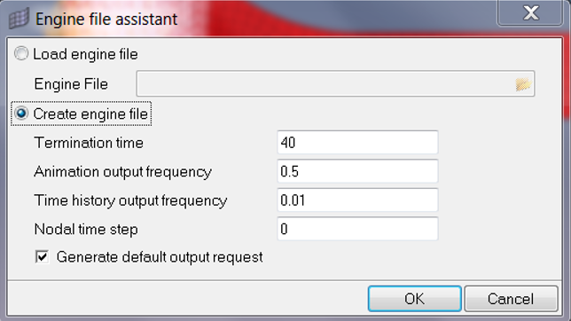
Create Output Requests
For this exercise the output request will be generated from the Engine file assistant,
which is located in the Utility Browser.
To start the Engine file assistant, select Tools > Engine File Assistant.
Input the values, as shown below:
Figure 10. Settings and Output Variables for the Engine
File
Export the Model
From the File menu, click Export > Solver Deck or click the Export Solver Deck icon
.
For File, click the folder icon and navigate
to the destination directory where you want to export to.
Enter the name TENSILE_0000.rad and click
Save.
Click the downward-pointing arrows next to Export options to expand the panel
and make sure “Auto export engine file” is checked.
Click Export and then click
Close.
Open Altair Compute Console from Start menu.
Select the TENSILE_0000.rad for the Input file.
Click Run.
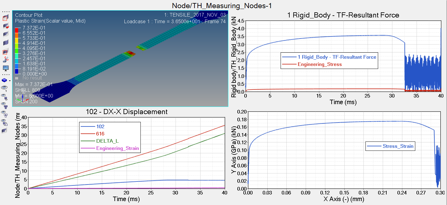
Review the output files for this run and verify the results. See if there is
any warning or errors on the .out files.
Using HyperGraph, plot the displacement and stress
curve (lower left and right) and the X-Force from the Rigid Body (upper
right).
 icon in toolbar.
 .
.
 to open the tensile_start_0000.rad file you saved to your working directory
from the radioss.zip file.
to open the tensile_start_0000.rad file you saved to your working directory
from the radioss.zip file.
 .
.