Cohesive Zone Modeling
Cohesive zone modeling can be used to model adhesive and bonded interfaces and corresponding crack initiation and propagation. There are multiple methods using adhesive and bonded interfaces which can currently be modeled in OptiStruct.
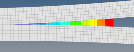
Figure 1.
Depending on the method, thickness of the adhesive/bonded interface can be defined (for damage model-based cohesive elements). The locations where cracks are expected should be identified and defined as cohesive zones.
Adhesive/Bonded Interface Implementation Methods
Cohesive zones are used to model Adhesive/Bonded Interfaces, which are typically locations where parts are connected with a glue or glue-like material.
- Traction-Opening Curves Method
- Damage Models Method
Traction-Opening Curves Method
Traction-Opening Curves can be directly defined on the MODEL field of the MCOHE Bulk Data Entry.
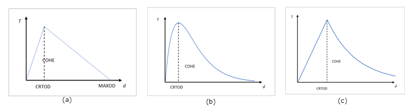
Figure 2. Traction-Separation Curves Available. (a) bilinear; (b) exponential; and (c) linear exponential
For the Traction-Opening Curves Method, only a single layer of cohesive elements are allowed to model a particular adhesive or bonded interface.
Typically, tensile and shear deformation at the interface are of interest to determine the integrity and/or degradation of the adhesion/bonding. Stiffness in compression is controlled via the SFC field on the MCOHE entry.
The relative displacement between the nodes of the top and bottom faces are calculated.
- , , and
- Are the relative displacements of the top and the bottom faces of a cohesive element along elemental x-, y-, and z-axes.
- Is the mixing coefficient, which can be input on the BETA field.
Using this combined relative displacement (), the combined traction is determined based on the chosen traction-opening curve (MODEL filed on MOCHE).
Damage Model Method
Damage Model method allows modeling of finite thickness of adhesive/bonded interfaces. This allows for modeling adhesive surfaces based on experimental data. In addition, damage initiation and propagation/evolution can be modeled.
MCOHED, DMGINI (Damage Initiation), and DMGEVO (Damage Evolution) entries are mandatory. Depending on the modeling technique (Element-based vs Contact-based), either CIFHEX/CIFPEN/PCOHE entries or CONTACT interfaces are required. Refer to Modeling Techniques.
Penalty stiffnesses in three directions can be defined on the KZ, KX, and KY fields of the MCOHED entry, in which KZ is for normal direction, KX and KY are for two tangential directions. Single or multiple layers of cohesive elements can be defined in the interface.
For Element-based modeling, the thickness of the cohesive element layer can be defined using the THICKNESS field on PCOHE. For Contact-based modeling, the thickness of the cohesive zone is considered internally to be equal to 1.0.
Typically, tensile and shear deformation at the interface are of interest to determine the integrity and/or degradation of the adhesion/bonding. Stiffness in compression is controlled via the SFC field on MCOHED entry.
The DMGINID and DMGEVOID fields on MCOHED can be used to identify the mandatory DMGINI and DMGEVO Bulk Data Entries in element-based modeling. When contact based modeling is used, stiffness in compression is determined by contact property.
The relative displacement between the nodes of the top and bottom faces are calculated (similar to the traction-opening method). First, the trial traction values () are calculated by multiplying the elastic moduli and relative displacements in each of the three directions.
Next, the determination of damage initiation is carried out, using the specified criteria on the CRI field of the DMGINI entry.
Strain-Based Criteria
- The maximum strain value is defined on the V1, V2, V3 fields of the DMGINI entry.
- The actual strain is calculated by the formula: (relative displacement divided by thickness). Where, the thickness is defined by the THICKNESS field on PCOHE.
- Using both maximum strain and actual strain, the Damage initiation determination
is done based on the following formula:
- MAXE
-
(2) Where,- Is V1.
- Is V2.
- Is V3.
- QUADE
-
(3) Where,- Is V1.
- Is V2.
- Is V3.
Stress-Based Criteria
- The maximum stress value is defined on the V1, V2, V3 fields of the DMGINI entry.
- The actual stress is the value of trial traction in each of the corresponding three directions.
- Using both maximum stress and actual stress, the damage initiation
determination is done based on the following formula:
- MAXS
-
(5) Where,- Is V1.
- Is V2.
- Is V3.
- QUADS
-
(7) Where,- Is V1.
- Is V2.
- Is V3.
In the formula above, the x-, y- and z-directions are in material coordinate system (refer to MCOHED card). The z-direction is the normal direction and x- and y- directions are two tangential directions.
If damage initiation criteria are not satisfied, there is no damage. Trial traction is equal to actual traction.
Therefore, there is no crack initiation and propagation and the corresponding cohesive-related output are printed to the result files.
- Displacement-Based Damage Index (TYPE=COHDISP on DMGEVO entry)
- Energy Dissipation-Based Damage Index (TYPE=COHENRG on DMGEVO entry)
For either type of damage index calculation, either linear (SHAPE=LIN) or exponential (SHAPE=EXP), shapes of the traction-opening curve can be used on the DMGEVO entry.
Displacement-Based Damage Index
If SHAPE = LIN:
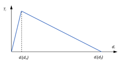
Figure 3.
If SHAPE=EXP
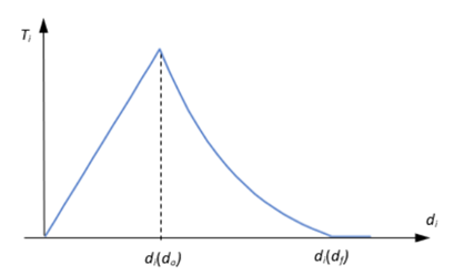
Figure 4.
- Is the maximum separation () in history. If the cohesive zone is only being loaded, then is equal to the current , which is calculated by OptiStruct and updated at each step. If cohesive zone is also unloaded, then within the unloading zone, is equal to the maximum in history (as it could be a previous value of , prior to the beginning of unloading).
- Is the critical separation (the separation, , when damage is initiated – when the crack initiation criteria are satisfied).
- Is the maximum separation ().
- Is the ALPHA field on DMGEVO entry.
- Is the current opening at each step of the solution.
- Is the W1 field on the DMGEVO entry.
- , , and
- Are the relative displacements of the top and the bottom faces of a cohesive element along elemental x-, y-, and z-axes.
Energy Dissipation-Based Damage Index
For Energy Dissipation-based Damage Index, the critical total energy ( ) is the key value used for calculations. Its calculation and usage depend on the type of curve (LIN/EXP) and the mode mix method (MMXFM = blank, 1,2). represents the energy at which failure occurs.
W1, W2, and W3 fields on the DMGEVO entry define the critical energies in each of the three fracture modes (normal, in-plane shear, and out-of-plane shear, respectively).
- Normal Fracture mode:
- Mode 1
- In-Plane Shear Fracture mode:
- Mode 2
- Out-of-Plane Shear Fracture mode:
- Mode 3
is the elastic energy absorbed by cohesion. It is the area under the straight line section (before damage initiation) of the exponential curve.
Where, is the damage index (it is always ≤ 1.0).
If SHAPE = LIN:
- Is the maximum separation () in history. If the cohesive zone is only being loaded, then is equal to the current , which is calculated by OptiStruct and updated at each step. If cohesive zone is also unloaded, then within the unloading zone, is equal to the maximum in history (as it could be a previous value of , prior to the beginning of unloading).
- Is the critical separation (the separation, , when damage is initiated – when the crack initiation criteria are satisfied).
- Is the separation at which zero traction is produced in analysis.
- Is the effective traction when crack initiation criteria are satisfied.
- Depends on the mode mix form (MMXFM field on DMGEVO entry).
- If MMXFM field is blank:
(14) - If MMXFM field is set to 1 (Power Law): The is derived from:
(15) Where, , , and are the W1, W2, and W3 fields on the DMGEVO entry.The value of is derived as:(16) Where,- Is the ALPHA field on DMGEVO entry.
- , , and
- Are the W1, W2, and W3 fields on the DMGEVO entry.
- , , and
- Are the relative displacements of the top and the bottom faces of a cohesive element along elemental x-, y-, and z-axes.
- If MMXFM field is set to 2 (BK Form):The value of is based on the following equation:
(17) Where,- Is the ALPHA field on DMGEVO entry.
- and
- Are the W1 and W2 fields on the DMGEVO entry.
If SHAPE=EXP:
- Is the compound traction.
- Is the elastic energy absorbed by the cohesion.
- Is the critical separation (the separation, , when damage is initiated – when the crack initiation criteria are satisfied).
- Is the final separation.
- Is the total energy that can be dissipated by cohesion under the current opening pattern (combination of , , and ). The released energy, , is calculated automatically by OptiStruct and depends on the mode mix form (MMXFM field on DMGEVO entry) and the energy that can be dissipated in each mode (W1, W2, and W3).
- If MMXFM field is blank:
(19) - If MMXFM field is set to 1 (Power Law):The is derived from:
(20) Where,- , , and
- Are the W1, W2, and W3 fields on the DMGEVO entry.
- , , and
- Are the energies under the curve until the current step. They depend on the type of curve (LIN/EXP).
However, by default, the same value of as the linear curve is used for the exponential curve for Power law.(21) Where,- Is the ALPHA field on DMGEVO entry.
- , , and
- Are the W1, W2, and W3 fields on the DMGEVO entry.
- , , and
- Are the relative displacements of the top and the bottom faces of a cohesive element/contact along elemental/local x-, y-, and z-axes.
- If MMXFM field is set to 2 (BK Form):The value of is:
(22) Where,- Is the ALPHA field on DMGEVO entry.
- and
- Are the W1 and W2 fields on the DMGEVO entry.
Calculating Actual Traction
Actual traction is calculated as follows, based on the Damage Index calculation selected above.
- and
- Are the initial elastic stiffness and opening in the i-direction respectively.
- Is the thickness defined in the PCOHE entry.
This actual traction is then subsequently used for the solution.
Cohesive Element Erosion
When damage index of all integration points in a cohesive element reaches the value defined on the MXDMG field in MCOHED card, and none of these integration points is in compression, the cohesive element is eroded and do not work in the rest analysis in the current subcase and the continued subcases.
Modeling Techniques
- Defining Cohesive Elements Directly (CIFHEX/CIFPEN elements)
- Contact-based method (CONTACT entry)
Defining Cohesive Elements (CIFHEX and CIFPEN elements)
- The main focus of the CIFHEX and CIFPEN elements is the relative movement between the top and bottom faces.
- The relative displacement between the nodes of the top and bottom faces at
each integration point in each of the three directions (elemental X, Y, Z)
determines the cohesive opening.
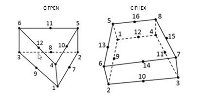
Figure 5. - Traction provides the tensile and shear stiffness and SFC
field on the PCOHE entry identifies the compressive
stiffness for cohesive elements.Note: Traction calculation depends on the method used for Adhesive/Bonded interface modeling.
- Refer to Interface Elements for more information on the cohesive element formulation.
- Cohesive elements should be inserted in the path of crack propagation.
- For Traction-Opening Method, only a single layer of cohesive elements should be used.
- For Damage Model Method, multiple layers of cohesive elements can be used.
- CIFHEX and CIFPEN elements are available for modeling cohesive elements.
- Cohesive elements can only be connected to shell or solid elements of the base model.
- If an exact one-on-one nodal correspondence, along with the exact same mesh density exists between the cohesive element layer and the shell/solid connecting layer of the base model, then the nodes can be shared (equivalenced) and no contact definition is required.
- If such an exact one-on-one nodal correspondence does not exist, the CONTACT(FREEZE) or TIE connection should be used to connect the cohesive elements on either top/bottom layer to the corresponding shell/solid elements of the base model.
- Cohesive elements may have a geometrical thickness in the interface. For the Traction-Opening method, a thickness of 1.0 is internally used automatically, regardless of the geometric thickness. For the Damage Model method, the THICKNESS field on PCOHE can be used to control the thickness interpretation.
- In some cases, it may be difficult for analysis with cohesive elements to converge. Damping stabilization can be introduced in the cohesive elements to help convergence. The damping stabilization can be defined by VED on MCOHE and MCOHED entries. Damping stabilization is currently not available in cohesive contact.
Contact-Based Technique (CONTACT entry)
The Contact-based technique does not require the use of cohesive elements (CIFHEX/CIFPEN) to model the cohesive zone. This technique allows simplification of the model setup, as it eliminates the need to mesh and setup the cohesive elements.
The COHE continuation line on the CONTACT Bulk Data Entry can be used to activate the Contact-based method for cohesive zone modeling. The MCOHEDID field references the MCOHED identification number and therefore identifies the contact interface as an adhesive/bonded interface.
Only Damage Model Method is available for CONTACT-based modeling. Also, the thickness of the cohesive zone is internally always set to 1.0 for this method.
Contact penalty is used to avoid penetration in compression. Contact effects are ignored, and cohesive effects are activated in separation.
Currently only SMALL sliding, frictionless, N2S/S2S contact is supported for cohesive modeling.
Supported Solution Sequences
- Nonlinear Static Analysis (SMDISP and LGDISP)
- Nonlinear Transient Analysis (SMDISP and LGDISP)
- Mass is not considered in cohesive elements.
- Linear Analysis, including static, transient, buckling, and eigen mode
analysis
- Cohesive effects are not available for Linear Analysis.
- The initial stiffness of cohesive elements is used in linear analysis. The initial stiffness is determined by the MCOHE or MCOHED entry (the initial slope of the traction-separation curve defined in MCOHE entry or the Ki value defined in the MCOHED entry.
- There is no crack propagation/initiation.
- There are no cohesive elements related output for Linear Analysis.
- Cohesive elements are currently only supported for Implicit Analysis. Explicit Analysis is not supported.
Output
Output from the cohesive zone is currently only available in H3D format.
- Cohesive Damage Initiation Index
- This item is shown in cohesive elements and secondary surface of cohesive contact.
- Cohesive Damage Index (Damage Index)
- This item is shown in cohesive elements and secondary surface of cohesive contact.
- Cohesive Energy by Mode (Dissipated Cohesive Energy by Mode)
- Cohesive Energy is output in terms of 3 modes (Mode I, II, and III)
- This item is not available in cohesive contact
- Cohesive Energy per Area by Mode (Dissipated Cohesive Energy per Area by
Mode)
- Cohesive Energy per area is output in terms of 3 modes (Mode I, II, and III)
- This item is not available in cohesive contact
- Cohesive Maximum Opening in History (Maximum Opening)
- This is the maximum relative displacement in history.
- This item is not available in cohesive contact.
- Cohesive Opening(s)
- This provides output for relative displacement in local elemental system and basic system.
- Cohesive Status (Status)
- Indicates element loading/unloading/fail state
- 0: Loading
- 1: Unloading/Reloading
- 2: Fail
- Cohesive Traction (Traction)
Eroded cohesive elements are not shown in h3d output from its eroded analysis time. Therefore, the above items are not available in eroded cohesive elements.
In cohesive zone output when contacts are used to model the cohesive zone, cohesive traction and cohesive opening are listed in label ‘Contact Traction / Normal’, ‘Contact Traction / Tangent’, ‘Contact Deformation / Normal’ and ‘Contact Deformation/Tangent.’ In order to keep it consistent with contact pressure, cohesive normal traction is shown as negative value in ‘Contact Traction / Normal.’