|
»Click here to display Table of Contents«
|

Visualization Toolbar |

|

|

|

|
|
Visualization Toolbar |
|
|
|

|
|
»Click here to display Table of Contents«
|
Visualization Toolbar |
|
|
|
|
|
Visualization Toolbar |
|
|
|
|
The Visualization toolbar controls the rendering of entities in the graphics area, and includes settings for geometry and mesh color mode. You can turn on/off the Visualization toolbar from View > Toolbars.
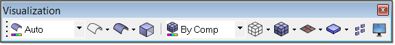
The detailed behavior of each tool button is described in the following table:
Button |
Left-click |
LEFT Behavior |
Right-click |
RIGHT Behavior |
|
Pick a different mode |
Automatically selects one of the following color modes based on the currently active panel. You can change all of the colors in the Options > Colors panel. To access this panel, click Preferences > Colors from the menu bar, or press <o>. |
Same |
|
|
Pick a different mode |
All surfaces are colored based on the assemblies they belong to. Each assembly receives a different color (although models with many assemblies may have colors repeated for more than one assembly). Any surfaces that do not belong to an assembly are colored gray. To change an assembly's color, right-click its color box in the Model browser or Entity Editor and select a new color. |
Same |
|
|
Pick a different mode |
Changes the color of all surfaces and solid faces to the color assigned to the component in which that geometry resides. All surface edges and solid face edges are colored black. A component's color can be changed in the Model Browser > Component View. |
Same |
|
|
Pick a different mode |
Surfaces are colored gray (2D faces (topo) with surface edges colored by topology: red (free edges), green (shared edges), yellow (t-junctions), or blue (suppressed edges). Solid faces and face edges are colored transparent green (bounding faces) with internal faces colored yellow (full partition faces). |
Same |
|
|
Pick a different mode |
Surfaces are colored gray (2D faces (topo) with surface edges colored by topology: red (free edges), green (shared edges), yellow (t-junctions), or blue (suppressed edges). Solid faces and face edges are colored blue, ignoring solid topology. |
Same |
|
|
Pick a different mode |
Surfaces and surface edges are colored blue, ignoring surface topology. Solid faces and face edges are colored transparent green (bounding faces) with internal faces colored yellow (full partition faces). |
Same |
|
|
Pick a different mode |
Surfaces are colored by component with surface edges colored by topology. Solid faces are colored by component with solid face edges colored by topology. |
Same |
|
|
Pick a different mode |
Surfaces display in wireframe mode, with surface edges colored blue (ignoring topology). Solid faces are colored by mappability: red (not mappable), yellow (1d mappable), or green (3d mappable). Solid face edges are colored by topology. |
Same |
|
|
Shaded Geometry with Surface Edges |
Button: set geometry mode to shaded with surface edges. Arrow (lower-right): Select option from menu |
Same |
|
|
Shaded Geometry |
Button: set geometry mode to shaded. Arrow (lower-right): Select option from menu |
Same |
|
|
Wireframe Geometry with Surfaces Lines |
Button: set geometry to wireframe with surface lines. Arrow (lower-right): Select option from menu |
Same |
|
|
Wireframe Geometry |
Button: set geometry to wireframe mode. Arrow (lower-right): Select option from menu |
Same |
|
|
Transparency |
Opens the Transparency panel. |
Same |
|
|
Pick a different mode |
All elements are colored by the color assigned to the component in which that element resides. A component's color can be changed in the Model Browser by right-clicking its color box and picking a new color. |
Same |
|
|
Pick a different mode |
All elements are colored by the property assigned to that element. Properties are assigned to elements directly or indirectly. Properties are assigned directly to the element by using the Property > Assign panel. Indirect element properties are inherited from the component in which the element resides; component properties are assigned in the Component > Assign panel. Directly assigned properties override indirect ones. Solvers in group #1 (RADIOSS (Bulk Data), OptiStruct, Nastran) can support both direct and indirect element property assignment. Solvers in group #2 (RADIOSS (Block), LS-DYNA) only support indirect element property assignments. Any element without a property is colored gray. A property's color can be changed in the Model Browser by right-clicking its color box and picking a new color. |
Same |
|
|
Pick a different mode |
All elements are colored by the material assigned to that element. Materials are assigned to elements differently for solver group #1 and solver group #2; Solver Group #1 (RADIOSS (Bulk Data), OptiStruct, Nastran) assign materials to properties, and then properties to elements (either directly or indirectly as discussed in Color by Property). Elements with both direct and indirect property assignments use the material associated with the direct element property assignment. Solver group #2 (RADIOSS (Block), LS-DYNA) assigns materials to elements indirect by assigning materials to the component in which the element resides using the Component > Assign panel. Any element which does not have a material assigned to it, directly or indirectly, will be colored gray. A material's color can be changed in the Model Browser by right-clicking its color box and picking a new color. |
Same |
|
|
Pick a different mode |
All elements are colored based on the assemblies they belong to. Each assembly receives a different color (although models with many assemblies may have colors repeated for more than one assembly). Any elements that do not belong to an assembly are colored gray. An assembly's color can be changed in the Model Browser by right-clicking its color box and picking a new color. |
Same |
|
|
Pick a different mode |
All elements are colored by their topology: green (1D), blue (2D), and red (3D). |
Same |
|
|
Pick a different mode |
All elements are colored by their element configuration (mass, reb2, spring, bar, rod, gap tria3, quad4, tetra4, etc.). An element's configuration color can be changed from the Element Types panel. |
Same |
|
|
Pick a different mode |
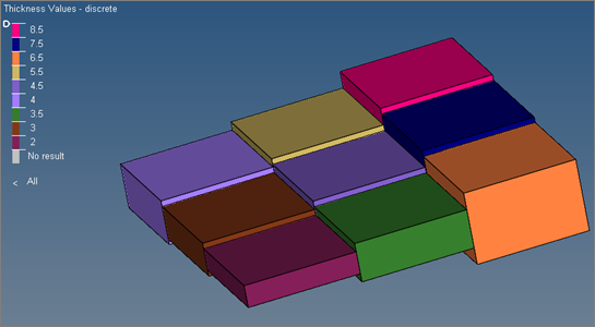
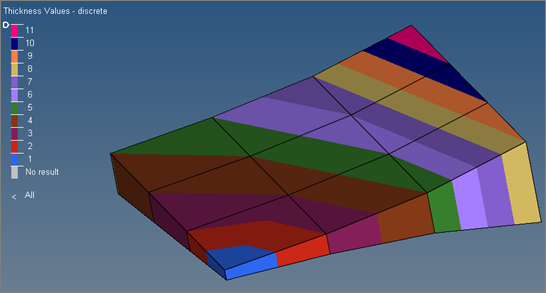
Shell elements are colored according to their thickness values (element or node); if no thickness is specified for any element or node, then they will all be the same color. However, elements with thickness values are colored individually according to their thicknesses. A key to indicate which thickness corresponds with each color displays in the corner of the graphics area. If the element is assigned with nodal thickness, then the nodes will be colored based on the thickness.
Element Thickness 2D Detailed Representation
Nodal Thickness 2D Detailed Representation This feature works in conjunction with the 2D Detailed Element display option described below. |
Same |
|
|
Pick a different mode |
Left-click the tool button to open the Element Quality View mode in the graphics area. This permanent mode serves as a useful tool to investigate each specific element criteria, as well as evaluate the overall quality of a mesh. |
Same |
|
|
Pick a different mode |
All elements are colored based on the domains they belong to. A domain is a morphing entity which enables design changes to an existing FE topology. Each domain receives a different color. Any elements that do not belong to a domain are colored gray. A domain color can be changed in the Model Browser by right-clicking its color box and picking a new color. |
Same |
|
|
Shaded Elements with Mesh Lines |
Set current element visual mode to shaded with mesh lines. Elements are shaded, and surface mesh lines display. Left-click the lower right arrow to expand the Options Menu. |
Select option from menu |
Right-click to expand Options Menu; Left-click an icon to set new current icon and perform icon’s left behavior. |
|
Shaded Elements with Feature Lines |
Set current element visual mode to shaded with feature lines. Elements are shaded but have no mesh lines, while feature lines display. Left-click the lower right arrow to expand the Options Menu. |
Select option from menu |
Right-click to expand Options Menu; Left-click an icon to set new current icon and perform icon’s left behavior. |
|
Shaded Elements |
Set current element visual mode to shaded. Elements are shaded, but no lines display. Left-click the lower right arrow to expand the Options Menu. |
Select option from menu |
Right-click to expand Options Menu; Left-click an icon to set new current icon and perform icon’s left behavior. |
|
Wireframe Elements (skin only) |
Set the current element visual mode to wireframe (skin only). Internal mesh lines will not display. Left-click the lower right arrow to expand the Options Menu. |
Select option from menu |
Right-click to expand Options Menu; Left-click an icon to set new current icon and perform icon’s left behavior. |
|
Wireframe Elements |
Set the current element visual mode to wireframe. Internal and surface mesh lines display. Left-click the lower right arrow to expand the Options Menu. |
Select option from menu |
Right-click to expand Options Menu; Left-click an icon to set new current icon and perform icon’s left behavior. |
|
Transparent Elements and Feature Lines |
Set current element visual mode to transparent with elements and feature lines. Elements are shaded but transparent, no mesh lines display, but feature lines do. Left-click the lower right arrow to expand the Options Menu. |
Select option from menu |
Right-click to expand Options Menu; Left-click an icon to set new current icon and perform icon’s left behavior. |
1D Traditional Element Representation |
Display a simple representation for 1D beam elements. |
Select option from menu |
Right-click to expand Options Menu; Left-click an icon to set new current icon and perform icon’s left behavior. |
|
1D Detailed Element Representation |
Display a more detailed, shaped-based representation for 1D beam elements. |
Select option from menu |
Right-click to expand Options Menu; Left-click an icon to set new current icon and perform icon’s left behavior. |
|
1D Traditional and Detailed Element Representation |
Display both the simple and detailed representations for 1D beam elements. |
Select option from menu |
Right-click to expand Options Menu; Left-click an icon to set new current icon and perform icon’s left behavior. |
|
2D Traditional Element Representation |
Display a simple representation for 2D shell elements. |
Select option from menu |
Right-click to expand Options Menu; Left-click an icon to set new current icon and perform icon’s left behavior. |
|
2D Detailed Element Representation |
Display a more detailed, shaped-based representation for 2D shell elements. |
Select option from menu |
Right-click to expand Options Menu; Left-click an icon to set new current icon and perform icon’s left behavior. |
|
2D Traditional and Detailed Element Representation |
Display both the simple and detailed representations for 2D shell elements. |
Select option from menu |
Right-click to expand Options Menu; Left-click an icon to set new current icon and perform icon’s left behavior. |
|
|
Layers off |
Ply layers are not displayed.
|
Select option from menu |
Right-click to expand Options Menu; Left-click an icon to set new current icon and perform the icon’s left behavior. |
|
Composite layers |
Plies in a composite material are displayed.
The exact nature of the display depends on the 2D Element Representation button. See Element and ply visualization for details. For continuum shells the display can be overlaid with the transparent representation of the original continuum shell elements, if 2D Traditional Element Representation ( |
Select option from menu |
Right-click to expand Options Menu; Left-click an icon to set new current icon and perform the icon’s left behavior. |
|
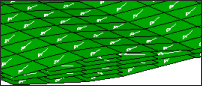
Composite layers with fiber direction |
Display layers with vectors indicating their appropriate ply orientation. Corrected fiber directions are shown if the drape data is available on every element of the ply.
The exact nature of the display depends on the 2D/3D element visualization button. See Element and ply visualization for details. For continuum shells the display can be overlaid with the transparent representation of the original continuum shell elements, if 2D Traditional Element Representation ( |
Select option from menu |
Right-click to expand Options Menu; Left-click an icon to set new current icon and perform the icon’s left behavior. |
|
Layer Edges |
Enables the ply lay-up or stack boundaries to be visualized, which provides an easy way to view ply drop-off. When the stack topology shape is changed, the visualization of the edges is automatically updated. Ply layer geometry edges are always outlined in white, where as FE edges are always outlined in the same color as the ply. FE edges are always outlined with a thicker line compared to geometry edges. |
|
|
|
Shrink Elements |
Left-click the tool button to toggle on/off shrink elements by shrink factor. Shrink factor can be set from the Options > Graphics panel. The Options panel can be accessed from the menu bar from Preferences > Graphics. |
Same |
|
|
Visualization Options |
Left-click the tool button to open Visualization Controls tab. |
Same |
|