Location: View > User Process
The User Process is a utility that lets you create, capture and re-run processes that you use frequently in HyperForm.
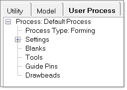
When you open a model in HyperForm, the User Process tree automatically populates with the applicable contents of your model. On the tree, a Tools section lists the model components and lets you define materials and contacts for each component. Each component has a context-sensitive menu, which you can access via right-click.
The following information takes you through the steps of adding and defining components in a process. In addition, several User Process templates are available in the Installation directory, including templates for multistage analysis, optimization studies, and more.
On the tree of the User Process tab, right-click Process Type, and then select from the options on the context menu.
For the Forming or Hot stamping option, an additional menu appears from which you can select a type specific to your forming process. After you select a forming process, the process setup is populated. Based on the process type selected, the number of tools becomes fixed and is not editable. If additional tools are required, change the Forming or Hot stamping option to User defined. Note that the available process is filtered based on the Blank type.
|
On the tree of the User Process tab, select Settings. To modify a setting, right-click it, and then select from the options on the context menu. For settings with numerical values, double-click the value, and then enter a new value. The settings available include the following:
Option
|
Action
|
Blank Type
|
Select Shell, Solid or Composite or Tube.
|
Blank Config
|
Select an option based on your blank type.
|
Symmetry
|
Select a symmetry setting.
|
Optimization
|
Select On or Off.
|
Animation: Count
|
Double-click the Count field to change its value, or right-click and change the value from the context menu.
|
Datum
|
Specify an object as a reference object so that when you perform an auto-position action, other objects are positioned relative to the reference object.
|
Draw Direction
|
Select a direction.
|
Motion Mode
|
Select Velocity or Displacement.
|
Memory Mode
|
Select Automatic or Manual.
|
Adaptivity
|
Select On or Off. For On, select an adaptivity level.
|
Thermal
|
Select On to activate the thermal properties settings. This feature is only available when the Blank Type is set to Solid or Shell.
|
|
Adding a Blank or Tube
The following information shows you how to create a new or add an existing blank/tube into your process.
To add a blank or tube from the Tools section
On the tree of the User Process tab, you can add a blank/tube to your process by moving an existing blank/tube from the Tools section into the Blanks/Tubes section.
| 1. | Right-click the blank/tube, and then select Switch Type. |
| 2. | Select Blank/Tube, and the blank changes from a Tool type to a Blank/Tube type, and the entry moves up to the Blanks/Tubes section. |
To create a new blank or tube
| 1. | Right-click Blanks/Tubes, and then select New Blank/Tube. A new blank/tube appears with the default name, Blank1 or Tube1. To rename the blank/tube, double-click it, and then enter a new name. |
| 2. | Right-click your new blank/tube, and then select a component. Alternatively, you can specify a component for the blank/tube from the File menu when setting up a multistage forming process. |
To create a contact for the blank
| 1. | Right-click Contacts, and then select Create New. Note that you can also use an existing contact in your process. |
Defining a Blank
The following options are available to define a blank:
Option
|
Action
|
Friction
|
Right-click, and then enter a value.
|
Conductance
|
Double-click, and then enter a value.
|
Material
|
Right-click to open the Material Database, and then select a material for the blank.
|
Position
|
If a model includes more than one blank, select a primary blank, and then select to position it above or below the other blanks. If only one blank is available, use the default setting, None.
|
Thickness
|
Double-click, and then enter a value.
|
Initial Temp
|
The Initial Temp displays when Thermal is set to On. To change the Initial Temp, double-click it, and then enter a new value.
|
Blank Type
|
For blank type, Composites, double-click and then enter a value for the following:
| • | Angle: Fiber angle: Angle for woven composites. |
| • | Fiber 1 angle: First fiber angle for woven composites. |
| • | Angle between fibers: Angle between the fibers in woven composites. |
|
Blank Config: Sandwich
|
| • | The sequence in the User Process is the Ply sequence, in which plies are stacked bottom to top after auto positioning. |
| • | You can move the Plies in the sequence up and down one level using the option Stack Order on the context menu. |
|
|
Adding a Tool
The following information shows you how to add a new tool to your process.
To create a new tool
| 1. | From the tree on the User Process tab, right-click Tools > New Tool. A new tool appears with the default name, Tool1. To rename the tool, double-click it, and then enter a new name. |
| 2. | Specify a component for the new tool: Right-click Tool1, and then select a component from the list. |
To create a contact for a tool
| 1. | Right-click Contact > Create New. |
| 2. | Right-click Material > Database, and then select a material for the contact. |
Defining a Tool
You can use the following options to define a tool:
Option
|
Action
|
Local Draw Direction
|
Right-click Local Draw Direction and then select on or off. If you set the local draw direction to on, you can manipulate the X, Y, Z direction for this particular tool only. For each tool in the User Process tab, you can set the Local Draw Direction. If a Tool has the Local Draw Direction option turned off, the default Z direction is applied as default.
|
Position
|
If the local direction is turned off for the tool, you can right-click Position to move the contact above or below the blank. If the local direction is turned on, select to, or not to, position the tool towards the blank along the direction. Enter a value for Clearance if an additional clearance relative to the contacting blank is necessary.
|
Loads
|
To create a new Motion or a new Force, right-click Loads.
| • | Motion: To set Motion properties, right click Motion > Properties. The Motion Properties dialog opens for you to enter values for the displacement function. To change the Velocity, click it, and then enter a new value. |
| • | Custom Animation: To add animation output based on the tool's distance from the bottom dead center, right-click Animation, and then select New. A new distance option appears with the value 0. To change the value, double-click it, and then enter a new value. |
| • | Force: To set the Force properties, right click Force > Properties. The Force Properties dialog opens for you to enter a value. To modify the Force, click it, and then enter a new value. |
| • | Stopper: To control tool motion while applying force, select Stopper from the Force context sensitive menu. The Stopper option lets you define a stopper location by selecting an element and defining stopper motion by via a target tool or by specifying the maximum displacement and velocity. Stopper is available for the Virtual Try-Out module only. |
| • | Auto Position: When you perform the Auto Position operation, the values associated with Auto Position automatically update. |
|
Temp
|
Temp displays when when the setting Thermal is set to On. To change the Temp value, double-click it, and then enter a new value.
|
Home Position
|
You can set any position or location of a tool in the global system as the home position. By default, when an object is selected as a tool, the position of the object is set as the home position.
|
Set
|
This options sets the tool's current position as its home position.
|
Return
|
This option retracts the tool from its current position to its home position.
|
Reject
|
This option moves the tool from it home position to its previous position. This option is active only when the Return action is performed.
|
|
The following information shows you how to add a guide pin to your process.
To create a guide pin tool
| 1. | From the tree on the User Process tab, right-click Tools > Guide Pins. A new guide pin appears with the default name, guidepin1. To rename the tool, double-click it, and then enter a new name. |
| 2. | Right-click the new guide pin, and then select a component for the guide pin from the list. |
To create a contact for the guide pin
Right-click Contact > Create New.
To attach the guide pin
Right-click Attachment, and then select the tool to which you want the guide pin to attach.
|
On the tree of User Process tab, right-click drawbeads. The Drawbead Editor opens for you to define drawbeads for your process.
|
Auto Positioning
Once you have defined all of the components in your process, and the relationships between the components, right-click and select Auto Position. The objects are positioned according to the relationships defined. An object defined in Datum is kept stationary while other objects move relative to it.
Display Options
You can apply Show, Hide, and Isolate display options to any objects in the graphics window.
|
After defining the settings for the components in your process, right-click and select Calculate distance. The distances are automatically calculated and updated in the User Process browser. If you want to manually set the displacement values for your process, you can skip this operation.
|
The save operation creates a template of your process. You can use the Load Process operation along with the template to run the same stamping process on a new set of meshed tools and a blank.
After defining the settings, tool and blank attributes, and loads for your process, select Save.
|
| 1. | Right-click, and then select Create Input. The process creates all of the input data that is required for the model simulation. |
| 2. | When the Create Input operation is completed, select Export to write the data to your current run directory. Alternatively, in the User Process tab, right-click and then select Run to launch the solver. |
|
The Auto Process functions work in conjunction with the User Process browser. If your model fits into one of the Auto Process setups, do the following:
From Auto Process, select Autoposition>Apply>Run. The values in the User Process browser automatically update with the results of the Auto Process configuration.
|
| 1. | From the View menu, select Process Sequence which displays the order of tasks in the process. You can drag-and-drop the tasks from left to right to alter their sequence. |
Note that an error message tab is available for you to review any errors that occur during the process.
| 2. | To close the Process Sequence dialog, from the View menu, select Process Sequence. |
|
See Also:
HyperForm Users Guide
HyperForm Settings


