|
»Click here to display Table of Contents«
|

Slice Editor |

|

|

|

|
|
Slice Editor |
|
|
|

|
|
»Click here to display Table of Contents«
|
Slice Editor |
|
|
|
|
|
Slice Editor |
|
|
|
|
This panel enables you to view the solution on planes cutting through the flow domain. The options available for this panel are:
Field |
Description |
Color by |
This selects the solution component to be displayed on the cutting plane. |
Slice # |
You can define and store up to 10 slicing planes at the same time. The number displayed by the slide bar indicates the slice number that can be manipulated using the Visibility option. |
Coordinates and Normal |
To draw a cutting plane, HyperXtrude requires a set of coordinates a point through which the cutting plane passes. Also, it needs the orientation of the cutting plane in the form of direction cosines. The default coordinates are the center of the object and the default direction cosines represent few plan views. |
Slice Visibility |
The check boxes for each slice allow you to display or erase solutions on cutting planes. |
Slice Viewport |
This provides an option to open a separate Slice Viewport to display the solution on the current cutting plane. You have an option of plotting the solution as a 3D carpet plot on these cutting planes. |
Carpet Plot Scale |
Controls the solution scale on the slicing plane. |
Display/Motion |
These options control the appearance of the colors on the slicing planes. The available options are: Transparent, Contour, Flat, Fog, Line, and Point. The transparent and contour options display the mesh on the plot. The displayed colors are vibrant with flat option. |
Apply |
Activates the current slice indicated by Slice #. |
Dismiss |
Closes the panel. |
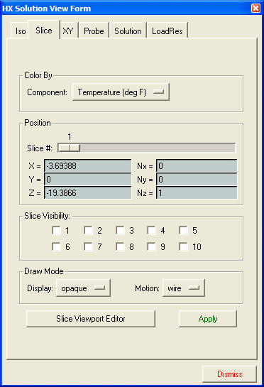
The Slice Editor panel