Load a *.hm file, that defines the tool geometry.
| 2. | Invoke the Tool Deflection Wizard from the Utility menu. |
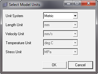
3 Click the Select Model Units checkbox. Select the suitable units in the window. Click OK to save and close the window.
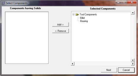
4. To generate the Tool Mesh, click the Generate Mesh checkbox. Select the tool components from the left hand side of the window and click Add.
| 5. | Click Next to proceed to meshing page. |
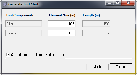
| 6. | Enter suitable element size for respective tool component and click Mesh. The respective component is highlighted, while entering its element sizes. |
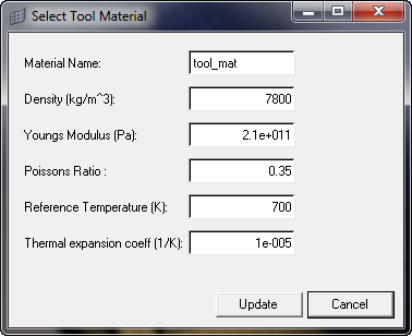
| 7. | Click the Select Material Data checkbox. Enter suitable material data and click Update to save and close the window. |
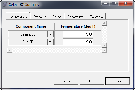
8. Click Create BCs to invoke the Select BC Surfaces dialog.
| a) | Enter suitable temperature value for each component and click Update. |
|
| a) | Pressure loads applied at surface level |
| b) | Select surfaces for pressure |
| c) | Enter suitable values for pressure on every surface. |
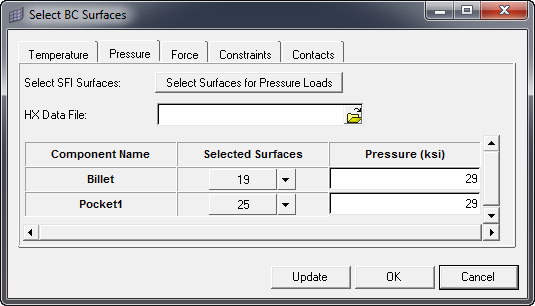
| d) | Pressure loads mapped from HyperXtrude results |
| e) | Select the surfaces for applying pressure loads |
| f) | Select *.hmascii data deck exported from HyperXtrude solver. |
| g) | All the Pressure (MPa) fields of surfaces will be disabled. Pressure data for every face will be applied from HX data. |
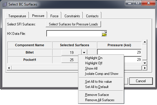
| h) | If you want to highlight a single surface, click on the corresponding surface and click Highlight On. |
| i) | If you want to remove single surface, click on the corresponding surface and click Remove Surface. |
|
| a) | Select the surfaces for applying force loads. |
| b) | Enter suitable magnitude and select suitable direction for force on every surface. |

| c) | If you want to highlight a single surface, click on the corresponding surface and click Highlight On. |
| d) | If you want to remove single surface, click on the corresponding surface and click Remove Surface. |
|
| a) | Select the surfaces for applying constraint loads |
| b) | Select the suitable directions for each surface |
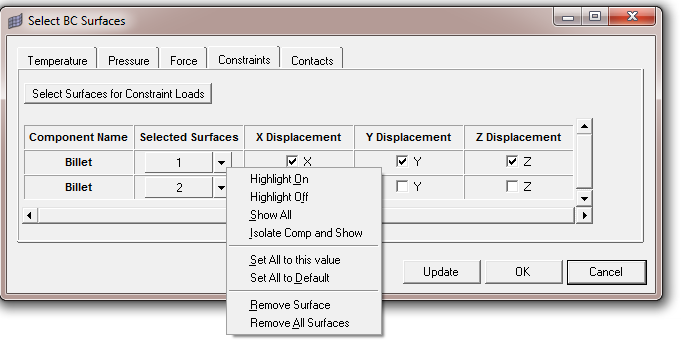
| c) | If you want to highlight a single surface, click on the corresponding surface and click Highlight On. |
| d) | If you want to remove single surface, click on the corresponding surface and click Remove Surface. |
|
| a) | Select the meshed components for creating gap contacts |
| b) | Enter suitable proximity distance and and break angle. |
| c) | Set All, Reset All and Remove All features does not apply to contact BCs. |
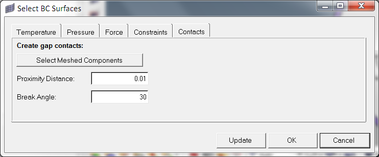
| d) | Click OK to complete the BC creation. |
|
7. Analyze
8. Post-process
Invokes HyperView by loading the results automatically.


