Deformation analysis of the tool allows the designer to determine where the tool is likely to deform and thereby, make corrections to the support.
There are three ways to do this analysis with HyperWorks. They are:
| • | Using HyperXtrude solver’s coupled flow, thermal and stress analysis |
| • | Using RADIOSS with the FEM file generated by HyperXtrude analysis (referred to in #1). HyperXtrude automatically writes this FEM file with the tool mesh, material data, and boundary conditions. This is a complete file and can be directly solved with RADIOSS. |
| • | Using the Tool Deflection Analysis wizard in the HyperXtrude user profile. This wizard helps you to create a model starting from solids. You can either specify assumed loads (pressure/force) or map the loads computed by HyperXtrude (just a flow analysis run). In addition, it can also do contact analysis. This interface uses the RADIOSS solver. However, no prior knowledge of RADIOSS or its native interface in HyperMesh is required. |
Tool Deflection Analysis via Wizard
| • | Uses assumed temperature and pressure/force loads |
| • | Assumed loads for pressure can be constant or vary linearly along extrusion direction. In addition, you can map the pressure loads using the solution computed by HX. |
| • | Problem set-up and analysis can be done in a few mouse clicks and less than 10 minutes |
| • | Targeted for die designers who are not CAE experts |
| - | You can use this wizard with very little training |
| - | No in-depth knowledge of HyperMesh and RADIOSS is required |
| - | Helps to setup and run a tool deformation analysis with few mouse clicks starting with CAD solids representing the tool. |
Process Steps in Tool Deflection Analysis
| 1. | Import the die geometry. Load a *.hm file that defines the tool geometry. |
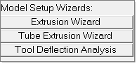
| 2. | Invoke the Tool Deflection Wizard from the Utility menu. |
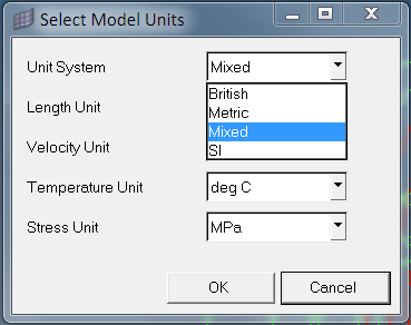
| 3. | Click on Set Model Units to open the window for selecting the model units. Select the units and then click OK to save the selected units. |
| 4. | Click the Generate Mesh checkbox. Select the tool components from the left hand side of the window and click Add. |
| 5. | Click Next to proceed to the meshing page. |
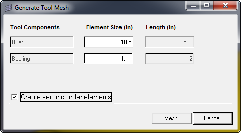
| 6. | Enter a suitable element size for the respective tool component and click Mesh. The respective component is highlighted, while entering its element sizes. Activate the checkbox if the second order element mesh needs to be generated. |
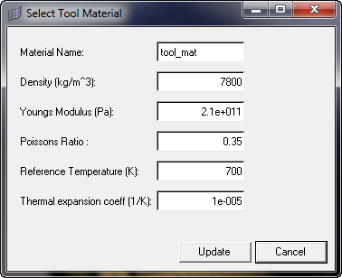
| 7. | Click the Select Material Data checkbox. Enter suitable material data and click Update to save and close the window. |
| 8. | Click Create BCs to invoke the BC creation. |
Highlight On
|
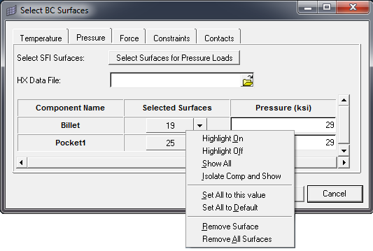
To highlight a surface, click the downward arrow button corresponding to each surface and click Highlight On.
|
Highlight Off
|
To turn off the highlighted surface, on the menu corresponding to each surface click Highlight Off.
|
Show All
|
Displays all the geometry of the selected components with surfaces
|
Isolate Comp and Show
|
To highlight a single surface, on the menu corresponding to each surface click Isolate Comp and Show.
|
Set All to this value
|
For temperature BC:
| • | Enter temperature for one component and click Set All to this value on the corresponding menu. This sets the same data for all components. |
| • | In order to reset all data to default, click Set All to Default on the corresponding menu. |
For Pressure, Force and Constraints
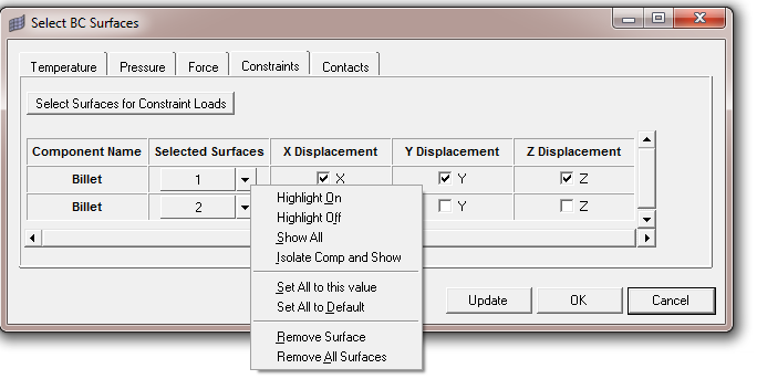
| • | Enter magnitude, select direction and displacements for one surface and click Set All to this value on the corresponding menu of the surface, to set same data for all surfaces. |
|
Set All to Default
|
To reset all the data to default, click Set All to Default on the corresponding menu of the surface.
|
Remove Surface
|
To remove a single surface, on the menu corresponding to each surface, click Remove Surface.
|
Remove All Surfaces
|
To remove all the selected surfaces, on the menu corresponding to each surface, click Remove All Surfaces.
|
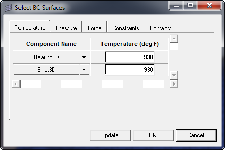
| 9. | In the Temperature BC tab, enter a suitable temperature value for each component and click Update. |
| 10. | On the Pressure BC tab- Pressure loads applied at surface level - Select surfaces for pressure. Enter suitable values for pressure on every surface. |
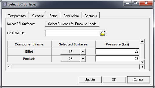
| 11. | On the Pressure BC tab - Pressure loads mapped from HyperXtrude results. Select the surfaces for applying pressure loads. |
| 12. | Select *.hmascii data deck exported from HyperXtrude solver. All the Pressure (MPa) fields of surfaces will be disabled. Pressure data for every face will be applied from HX data. |
| 13. | On the Force BC tab, select the surfaces for applying force loads. Enter suitable magnitude and select suitable direction for force on every surface. |

| 14. | On the Constraints BC tab, select the surfaces for applying constraint loads. |
| 15. | Select the suitable directions for each surface. |
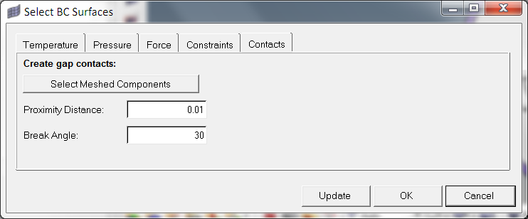
| 16. | On the Contacts BC tab, select the meshed components for creating gap contacts. |
| 17. | Enter suitable proximity distance and and break angle. Set All, Reset All and Remove All features does not apply to contact BCs. |
| 19. | Click Post-process to invoke HyperView by loading the results automatically. |


