Several panels require that you define a plane or a vector (direction) to perform a certain function. For example, the Translate panel requires that you define the direction of translation, while the Reflect panel requires a plane for the creation of the mirror images of the entities selected.
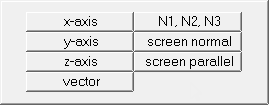
HyperForm takes advantage of the following principle: a plane can be defined with a vector (the plane is normal to the vector specified), just as a vector can be defined with a plane (the vector is normal to the plane specified). Either can be defined via the plane and vector selector — a group of buttons that work in concert to define planes or vectors, as needed:

The Plane and vector selector.
This selector is broken down into the following items. Note, however, that not every item appears at all times; only the items necessary for the current function will display.
Option
|
Description
|
switch 
|
The switch is used to select the method for defining the plane or vector. The options available are:
| • | Use x-axis, y-axis, and z-axis to define the first, second or third axis respectively of a coordinate system in your model. This coordinate system may be the global coordinate system, or a local system when one can be explicitly specified. Local systems may be rectangular, cylindrical or spherical. |
| • | Choose vector to specify a vector entity (created in the Vectors panel). This includes vectors defining coordinate systems, and loads as well. |
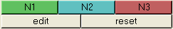
| • | Use N1, N2, N3 to define a vector (N1,N2), or plane (N1,N2,N3). When defining a plane, the resulting vector is normal to this plane following the right hand rule, and passes through either N1 or the base node (if one is specified). |
Double-click a node’s button (N1, N2, or N3, or B) to type in coordinates rather than selecting existing nodes in your model.
|
B (base node)
|
Use this selector to define the base node — the point in space where the vector or plane is located. For example, selecting a plane of projection using the x-axis does not define the location of the plane entirely. A base node provides the extra information.
Note that when using the N1, N2, N3 option, HyperMesh uses N1 as a default base node if no other base node is specified.
|
reset 
|
Allows you to clear your selection (vector, N1,N2,N3 and base).
|
| Note: | Some selectors may resemble the plane and vector selector, but serve a different purpose. For example, the following selector displays in the Position and Linear Solid panels: |
This selector is used in these panels to map entities from one location to another.
See also
Menu Buttons
Toggles & switches
Input Collectors
Input Fields
Pop-up Menus
Input Controls


