In this tutorial, you will learn how to:
| • | Load Moldex3D/Shell user profile |
| • | Load a HyperMesh file containing geometry of a part |
| • | Extract midsurface from the part geometry |
| • | Assign property card(s) to the part |
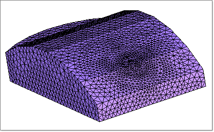
| • | Inspect mesh quality and thickness contour |
| • | Define melt entrance boundary condition |
| • | Export the model as a Moldex3D MSH file |
The model files for this tutorial are located in the file mfs-1.zip in the subdirectory \HyperMold\Moldex3D\MX_0020. See Accessing Model Files.
To work on this tutorial, it is recommended that you copy this folder to your local hard drive where you store your HyperXtrude data, for example, “C:\Users\Moldex3D\” on a Windows machine. This will enable you to edit and modify these files without affecting the original data. In addition, it is best to keep the data on a local disk attached to the machine to improve the I/O performance of the software.
| 2. | On the Preferences menu, click User Profiles. |
| 3. | In the Application field, select Manufacturing Solutions. |
| 4. | Select HyperMold and Moldex3D/Shell. |
|
| 1. | From the File menu, click Open. |
| 2. | Browse to the file MX_0020.hm. |
|
| 1. | In the Utility menu, under the Model Setup section, click Create Property Cards. A new macro page is displayed. |
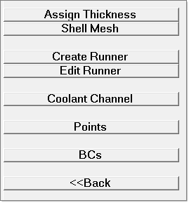
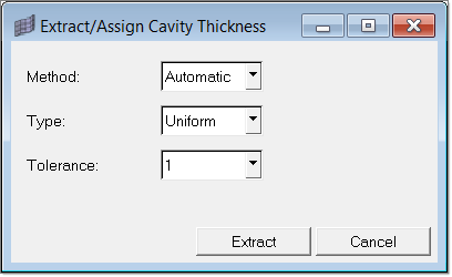
| 2. | Click Assign Thickness. The Extract/Assign Cavity Thickness dialog appears. |
| 3. | Set the Method: field to Manual. Enter a value of 2.0 in the Thickness field. |
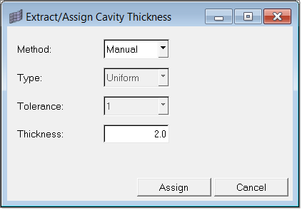
| 4. | Click Assign. The element selection panel is displayed. |
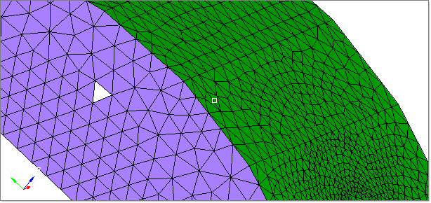
| 5. | With the yellow elems button activated, select any element on the top face. Then click elems >> by face. |
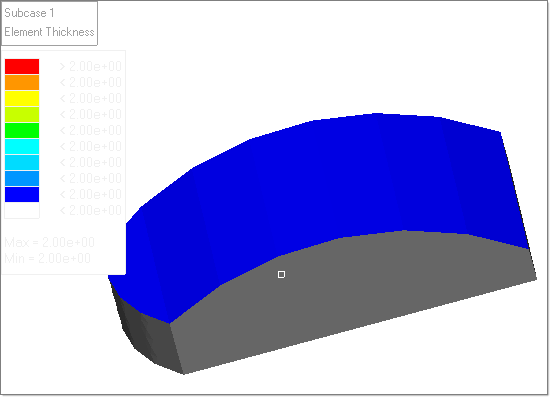
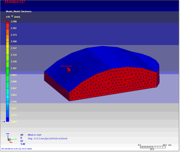
| 7. | In the panel, click Assign. The thickness is computed and a property card is assigned for each element. A contour plot appears in the graphics area that shows the distribution of element thicknesses. |
| 8. | Click return to close the panel. |
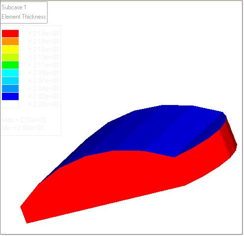
| 9. | Click Assign Thickness again. Set the Method to Manual and Thickness to 2.2. |
| 10. | Click Assign. Select one element on one of the faces adjacent to the top face. |
| 11. | Click elems >> by face. Click proceed. |
| 12. | Click return to close the panel. Repeat steps 10 and 11, selecting each the remaining sides until all sides are completed. |
|
| 1. | In the Utility menu, click Diagnostics. A new page opens. |
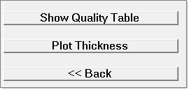
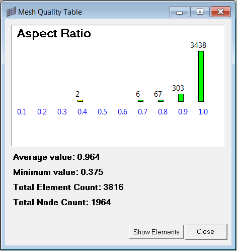
| 2. | Click Show Quality Table to see the mesh quality. |
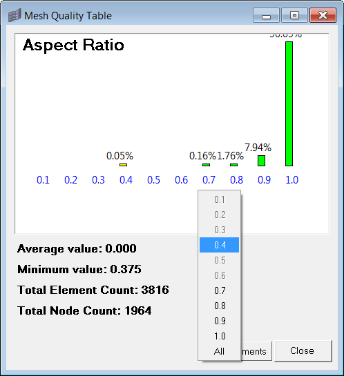
| 3. | Click Show Elements to see elements based on their Aspect Ratio values. |
| 4. | Click Plot Thickness to see the thickness contour. Click return to close this panel. |
| 5. | Click Back to return to the main Utility menu. |
|
| 1. | In the Utility menu, click Create Property Cards. |
| 2. | Click BCs. A panel to select the node will appear. |
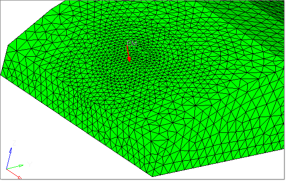
| 3. | In the graphics area, select a node on the part and click proceed. The Create Boundary Condition dialog appears. |
| 4. | Select Melt Entrance for BC type. Click OK. Notice the boundary condition on the node. |
| 5. | Click Back to return to the main Utility menu. |
|
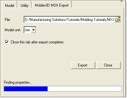
| 1. | Click Export. The Moldex3D MSH Export opens. |
| 2. | Specify the file path and name to write the MSH file and click Export. The export status is shown in the status bar. |
|
| 1. | Load the exported MSH file in Moldex3D solver. |
| 2. | Solve the model and post-process. |
|
Return to Moldex3D Tutorials


