In this tutorial you will learn to use the Extrusion Wizard with the meshed model.
Even though the Extrusion Wizard can mesh the model automatically, sometimes it may be required to start the analysis with an existing mesh. This typically happens when the model is complex and requires manual meshing to create a good quality mesh with fewer elements. Or, sometimes you can get a model with an existing mesh, which was created outside HyperMesh.
The model files for this tutorial are located in the file mfs-1.zip in the subdirectory \hx\MetalExtrusion\HX_0107. See Accessing Model Files.
To work on this tutorial, it is recommended that you copy this folder to your local hard drive where you store your HyperXtrude data, for example, “C:\Users\HyperXtrude\” on a Windows machine. This will enable you to edit and modify these files without affecting the original data. In addition, it is best to keep the data on a local disk attached to the machine to improve the I/O performance of the software.
| 1. | Select Start Menu > All Programs > Altair HyperWorks > Manufacturing Solutions > HyperXtrude to launch the HyperXtrude user interface. |
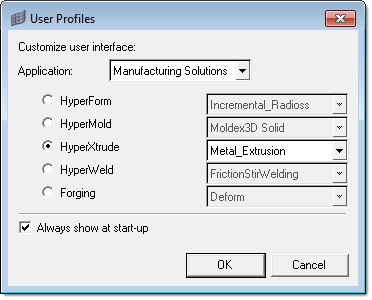
| 2. | The User Profiles dialog appears with Manufacturing Solutions as the default application. If it does not appear, you can access it from the menu bar by clicking Preferences > User Profiles. |
| 3. | Select HyperXtrude and Metal Extrusion. |
|
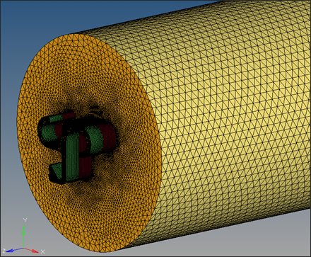
| 1. | Load the model HX_0107.hm. This model contains solid geometries for billet and bearing regions in the components Billet and Bearing. It contains the 3D mesh for the billet, bearing, and the profile regions in the components Billet3D, Bearing3D, and Profile3D. In addition, it contains the bearing lines required to create the bearing profile BC in the component BearlingLines, Bearing3D, and Profile3D. |
|
| 1. | On the Utility Menu, click Extrusion Wizard. Depending on how you loaded the model, the Project Browser may prompt you for additional action (see HX-0004 for details). |
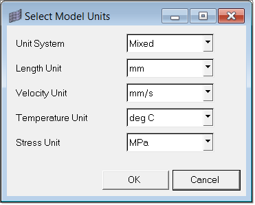
| 2. | In the Extrusion Wizard, click the Set Model Units checkbox. |
Note: Measure dimensions of the model by pressing F4 button on the key board to get an idea about the units of the model.
The length unit of the current model is inches (Billet diameter is about 6.65).
| 3. | Set the Unit System to Mixed and set the options as shown in the figure below. Click OK. |
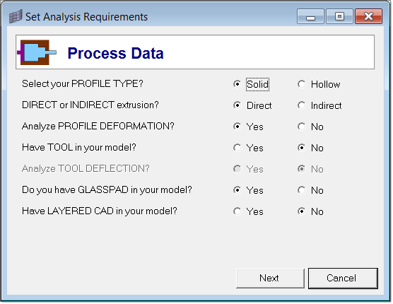
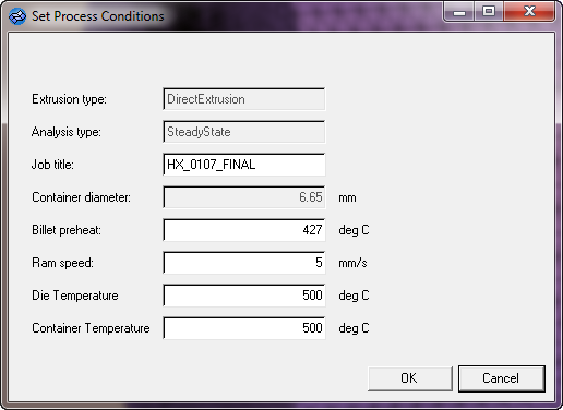
| 4. | Click Set Analysis Requirements and set the Process Data as shown in the figure below. Click Next. |
| 5. | In the Analysis Data page, click Yes on the last question, "Want to Control MESHING?" |
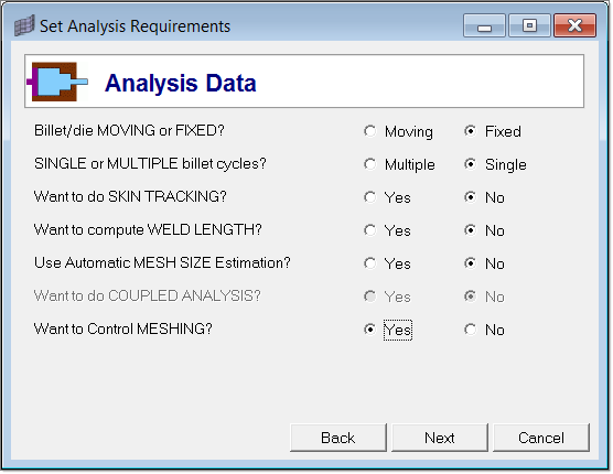
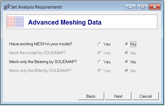
| 6. | Click Next to go to the Advanced Meshing Data page. |
| 7. | Click Yes to the first question, "Have existing MESH in your model?" This sets the other options to No automatically. |
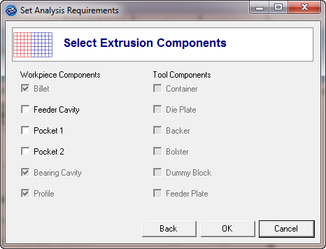
| 8. | Click Next to go to the Select Extrusion Components page. Verify that Billet, Bearing Cavity and Profile options are preselected. Accept the default conditions and click OK. |
In the Extrusion Wizard, you will skip the Select Press Data step as this model does not contain the information.
|
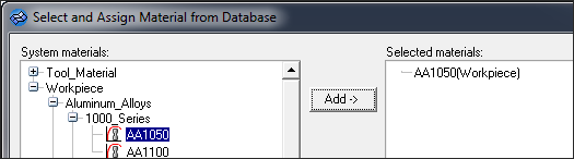
| 1. | Click Select Material Data. |
| 2. | Expand Workpiece, then expand Aluminum_Alloys and expand 1000_Series. |
| 3. | Select AA1050 and click Add-> to add the material under Selected Materials. |
You do not need to assign a material to the components while using the Extrusion Wizard. The selected materials will be assigned to the workpiece automatically.
|
| 1. | Click on the Set Component Information checkbox in the Extrusion Wizard. |
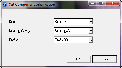
| 2. | Accept the selections and click OK to save the status. |
|
| 1. | Click Generate Workpiece BCs and accept the default conditions. |
| 2. | Click OK. This creates BC faces and associated load cards. |
|
| 1. | In the Extrusion Wizard, click on the Create Bearing check box. |
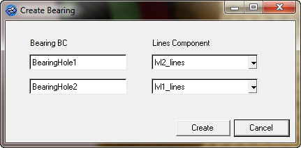
Verify whether the automatically selected line component for each bearing BC is correct. If not, select the correct one.
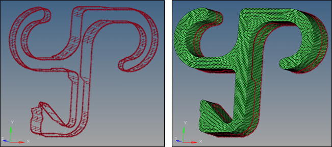
| 2. | Click on Create to create the bearing profile. The image on the left side shows the bearing profile and the one on the right side shows the bearing profile on top of bearing. |
|
This is an optional step and it is not required for this model. From the Utility Menu, you can inspect and change the boundary conditions and process parameters. In addition, you can also verify if the model has all the necessary boundary conditions, etc.
|
| 1. | In the Extrusion Wizard, click Save and Export the Model. |
| 2. | Export the model with the following: |
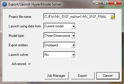
| 3. | Click Export to generate HX_0107_FINAL.grf and HX_0107_FINAL.hx files. |
The .hx and .grf files can be passed to the HyperXtrude solver for solving analysis.
| 4. | To launch the solver interactively, set Launch solver: to Interactive and then export. |
Alternatively, you can set Launch solver: to No and submit the job on e-compute.
|
Return to Metal Extrusion Tutorials


